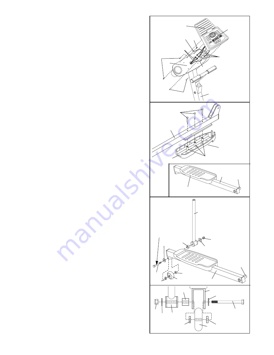
background image

8

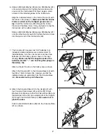
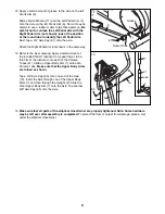
10. Identify the Left Pedal Arm (3), which has an ÒLÓ sticker

on it. 

Be careful not to confuse the Left Pedal Arm

with the Right Pedal Arm (not shown); look at the
position of the round tube in the inset drawing to
identify the Left Pedal Arm. 

Next, identify the Left

Pedal (41), which has the letter ÒLÓ molded onto the
bottom. 

Turn over the Left Pedal Arm (3) as shown. Insert the
three plastic posts on the Left Pedal (41) into the three
indicated holes in the Left Pedal Arm. 

Make sure that

the Left Pedal is turned as shown.

Attach the Left

Pedal with three M4 x 16mm Flange Screws (43).

Attach the Right Pedal (not shown) to the Right Pedal
Arm (not shown) in the same way.

10

43

3

41

Open Side

Plastic Posts

Open Side

Round

Tube

3

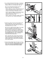
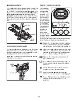
9. Connect the Extension Wire (51) to the corresponding

wire on the Console (87). 

Next, connect the two Pulse Wires (86) to the two
remaining wires on the Console (87). Note: Either
Pulse Wire can be attached to either wire on the
Console. 

Next, connect the ground wire to the indicated hole in
the Console Plate (91) with an M4 x 16mm Screw (35).

Carefully feed the wires down into the Upright (2).
Attach the Console Base (49) to the Upright with four
M4 x 16mm Screws (35). 

Be careful to avoid pinch-

ing the wires.

9

86

91

87

49

35

35

2

51

Console

Wires

35

Ground Wire

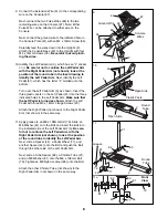
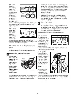
11. Apply grease to an M8 x 108mm Bolt (79). Slide an

M8 Washer (81) onto the Bolt and insert the Bolt into
the indicated side of the Left Pedal Arm (3). 

Be care-

ful not to confuse the Left Pedal Arm with the
Right Pedal Arm (not shown); look at the position
of the round tube to identify the Left Pedal Arm.

Next, slide a Spacer (44), a Pedal Wheel (77), and
another Spacer (44) onto the Bolt and push the Bolt
through the other side of the Left Pedal Arm.

Next, slide a Tube Spacer (82), a Chrome Tube (21),
and an M8 Washer (81) onto the M8 x 108mm Bolt
(79). Tighten an M8 Nylon Locknut (80) onto the Bolt.

Attach the other Chrome Tube (not shown) to the
Right Pedal Arm (not shown) in the same way.

21

81

82

79

81

44

44

77

80

11

3

Grease

Round

Tube

11a

79

44

44

77

3

81

81

80

21

82

Front

View

Summary of Contents for 695e

Page 1: ...r satisfaction If you have questions or if there are missing parts we will guarantee complete satisfaction through direct assistance from our factory TO AVOID DELAYS PLEASE CALL DIRECT TO OUR TOLL FRE...

Page 2: ...BEFORE YOU BEGIN 4 ASSEMBLY 5 HOW TO USE THE ELLIPTICAL CROSSTRAINER 10 MAINTENANCE AND TROUBLE SHOOTING 14 CONDITIONING GUIDELINES 15 PART LIST 18 EXPLODED DRAWING 19 HOW TO ORDER REPLACEMENT PARTS...

Page 3: ...llip tical crosstrainer do not arch your back 10 The pulse sensor is not a medical device Various factors including the user s move ment may affect the accuracy of heart rate readings The pulse sensor...

Page 4: ...al questions please call our Customer Service Department toll free at 1 800 999 3756 Monday through Friday 6 a m until 6 p m Mountain Time excluding holidays To help us assist you please note the prod...

Page 5: ...the parts bag check to see if it has been pre assembled 5 1 Hold the Rear Stabilizer 65 against the saddle on the rear of the Frame 1 Make sure that the Stabilizer is turned so the square holes are fa...

Page 6: ...lt 25 and an M10 Nylon Locknut 26 Do not overtighten the Nylon Locknut the Incline Bracket must pivot easily 24 25 26 2 4 Align the two holes in the front of the Upright 2 with the two welded bolts on...

Page 7: ...tending from the Upright 2 through the Console Plate 91 Be careful not to pinch the wires Push the two Bottle Holders 90 into the Console Plate 91 as shown 7 8 35 Wires Battery Clip Batteries 87 49 53...

Page 8: ...to either wire on the Console Next connect the ground wire to the indicated hole in the Console Plate 91 with an M4 x 16mm Screw 35 Carefully feed the wires down into the Upright 2 Attach the Console...

Page 9: ...nto one end of the Axle 19 Insert the Axle through one of the Upper Body Arms 7 and then through the Upright 2 Slide the other Upper Body Arm 7 onto the Axle Tap another 5 8 Axle Cap 85 onto the Axle...

Page 10: ...our exercise you may choose to turn the pedal disks in the opposite direction To dismount the elliptical crosstrainer wait until the pedals come to a complete stop Important The elliptical crosstraine...

Page 11: ...to help you reach specific exercise goals by pacing your exercise You can choose from a stamina building Interval program an Aerobic pro gram and a special Fat Burn program As you exercise seven monit...

Page 12: ...isplay will appear for two seconds the console will then be ready for use Note If batteries were just installed the power will already be on Select one of the three pacer programs or the manual mode T...

Page 13: ...in to flash and your heart rate will be shown For the most accurate heart rate reading continue to hold the contacts for about 15 seconds Make sure that your hands are positioned as described above an...

Page 14: ...embly step 7 on page 7 HOW TO LEVEL THE ELLIPTICAL CROSS TRAINER If the elliptical crosstrainer does not sit flat on the floor one or both of the leveling pads should be adjusted First loosen the jam...

Page 15: ...kout should include three important parts 1 a warm up 2 training zone exercise and 3 a cool down Warming up Warming up prepares the body for exercise by increasing circulation delivering more oxy gen...

Page 16: ...lles Stretch With one leg in front of the other reach forward and place your hands against a wall Keep your back leg straight and your back foot flat on the floor Bend your front leg lean forward and...

Page 17: ...17 NOTES...

Page 18: ...Screw 44 4 Spacer 45 2 Wheel 46 2 3 8 x 1 3 4 Button Head Screw 47 1 Left Side Shield 48 1 Right Side Shield 49 1 Console Base 50 1 Reed Switch Wire 51 1 Extension Wire 52 1 Reed Switch Bracket 53 6 P...

Page 19: ...75 58 80 49 31 66 16 26 13 12 15 14 26 28 63 4 42 43 43 44 44 78 78 76 61 63 76 74 9 9 6 83 40 33 33 67 67 17 17 38 68 70 89 34 36 80 38 39 37 48 71 73 73 35 35 77 35 56 35 47 2 7 7 18 19 20 21 21 22...

Page 20: ...not extend to any product or damage to a product caused by or attributable to freight damage abuse misuse improper or abnormal usage or repairs not provided by an ICON authorized service center produc...

Reviews: