background image

11

5.

For a 40 amp 240 volt AC power supply, set the
jumper J1 to pins 1 and 2 on the power board and
leave the other jumpers at the factory settings, as
shown at the right. This will allow the heater and
the pump to operate at high speed simultaneously.

6.

Secure the power cord by tightening the screws in
the wire clamp on the Control Unit (14).

11. Attach the access cover to the Spa Unit (15) by

inserting the top of the cover under the edge of the
spa shell. Be sure the 240 volt power cord is routed
through the notch in the cover. Slide the cover into
place and secure the cover with the four access
cover screws.

7.

Close the cover on the Control Unit and secure the cover with the two Control Unit Screws and the two
Small Star Washers removed in step 1.

8.

Install the 240 volt GFCI at the source voltage to conform with national electrical codes.

9.

Attach the power cord to the 240 volt AC power source. Be sure that the 240 GFCI is in place. 

10. Test the GFCI for proper operation.

5

14

Screws

Power Cord

Wire

Clamp

6

11

Jumper settings for a 240 volt AC,

40 amp power supply

Access

Cover

240 volt

Power Cord

Access Cover

Screws

Spa

Shell

15

Summary of Contents for 831.21005

Page 1: ...ave this manual for future reference SEARS ROEBUCK AND CO HOFFMAN ESTATES IL 60179 QUESTIONS PLEASE CALL DIRECT TO OUR TOLL FREE CUSTOMER HOT LINE The trained technicians on our customer hot line will provide immediate assistance free of charge to you CUSTOMER HOT LINE 1 800 999 3756 Mon ÐFri 6 a m Ð6 p m MST Hydrotherapy Spa Model No 831 210050 Serial No Write the serial number in the space above...

Page 2: ...terior attributable to freight mishandling damage resulting from improper winterization damage to the spa shell resulting from improper chemical treatment damage to the spa shell resulting from exposure to extreme temperatures or damage to the spa shell resulting from exposure to direct sunlight and ultraviolet rays while the spa is empty damage to the pump motor plumbing and components due to imp...

Page 3: ... The surface of the spa shell can reach temperatures as high as 150 F in a matter of minutes if exposed to the sun while it is empty These high temperatures can cause significant damage such as blistering of the shell surface and warping of the spa shell Any damage caused by sun exposure is not covered under warranty 9 Do not bring any object into the hydrothera py spa that could damage the spa sh...

Page 4: ...e hydrotherapy spa at all times Always replace and lock the spa cover when the hydrotherapy spa is not in use 27 DANGERÑRisk of drowning Exercise extreme caution to prevent unauthorized and unsupervised use of the hydrotherapy spa by children Children must always be super vised 28 WARNINGÑTo reduce the risk of injury The water temperature should never exceed 104 F 40 C Temperatures between 100 F 3...

Page 5: ...es to consult their physician before using this product 36 If you feel pain or dizziness at any time while using the hydrotherapy spa discontinue use and contact a physician 37 The included warning sign must be posted where all users of the spa can see and read it see POSTING THE WARNING SIGN on page 15 38 Never use soft water when filling the hydrotherapy spa Soft water is extremely corrosive to ...

Page 6: ...s throughout the body The RESTORA TION 5 1 hydrotherapy spa gives you the specialized treatment you need to feel your best For your safety and benefit read this manual care fully before using the PROFORM RESTORATION 5 1 If you have additional questions please call our Customer Service Department toll free at 1 800 999 3756 Monday through Friday 6 a m until 6 p m Mountain Time excluding holidays To...

Page 7: ... deck system that is built flush with the top of the spa provided you leave access to the motor for service 8 Be sure to note any other considerations such as aesthetics or privacy concerns which may affect the safety or enjoyment of using the hydrotherapy spa If you set up the hydrotherapy spa outside 1 You should check your local building codes con cerning the use of outdoor spas 2 The hydrother...

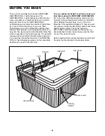
Page 8: ...es Remove the four access cover screws from the access cover Remove the access cover from the Spa Unit 15 by sliding the access cover down and pulling the bottom of access cover away from the Spa Unit Be careful not to damage the spa shell 2 Locate and check the position of the cut off valves Occasionally the valves will be closed at the factory during manufacturing The cut off valves must be open...

Page 9: ...e of the Spa Cover tight The Spa Cover must be tight Do not place the Buckle over one of the grooves in the wood panels Remove the latch Attach the Buckle to the side of the spa with two Buckle Screws 1 Note It may be helpful to use a drill with a 1 16Ó drill bit to make starter holes in the wood panels You may also want to apply a little soap or wax to the screw threads Attach the other three Buc...

Page 10: ... 2 and 3 on the power board and leave the other jumpers at the factory settings as shown at the right At 30 amps there is not enough amperage to operate the heater and the pump at high speed simultaneously Go to step 6 1 2 N White Blue Black Black Green Blue White Wire Nut L1 L2 14 4 Jumper settings for a 240 volt AC 30 amp power supply 10 WIRING THE RESTORATION 5 1 The RESTORATION 5 1 is designed...

Page 11: ...240 volt power cord is routed through the notch in the cover Slide the cover into place and secure the cover with the four access cover screws 7 Close the cover on the Control Unit and secure the cover with the two Control Unit Screws and the two Small Star Washers removed in step 1 8 Install the 240 volt GFCI at the source voltage to conform with national electrical codes 9 Attach the power cord ...

Page 12: ...ways keep the chemi cals away from children and pets The first time you use the spa you should test and treat the water You must also treat the water each time you refill the spa Once you have verified that the spa is functioning properly and the water has cir culated for a while remove the spa cover and add 1 3 of the ÒBromine BaseÓ bottle and 1 3 of the ÒNon chlorine ShoxÓ bottle to the water Al...

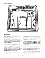
Page 13: ... on your lower or middle back The filter C can be removed for replacement and cleaning see CHECKING AND CLEANING THE FIL TER on page 16 The suction vents D located near the floor of the spa brings the water into the pump in order to operate the system The suction covers should always be in place over the suction vents Never operate the spa without the suction covers in place This spa is ozone read...

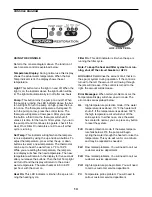
Page 14: ...hen the Set Temp light will turn off and the display will return to the actual water temperature The water heats at 6 0 to 8 0 F per hour with the cover on Heat On This LED indicator is lit when the spa is run ning the heating cycle Filter On This LED indicator is lit when the spa is running the filter cycle Note To keep the heat and filter cycles from run ning shut off the circuit breaker or GFCI...

Page 15: ...y a few The number of daily cycles as well as the length of the cycle can be adjusted The pump can run one to three filter cycles daily To change the number of cycles press the pump and up buttons at the same time The number of cycles will appear in the temperature display Use the up and down buttons to select the desired number of cycles Each cycle can run for 60 120 or 180 minutes To change the ...

Page 16: ...k best in your climate CLEANING THE SPA SHELL The spa shell should be cleaned with a mild soap solution Do not use solvents The spa should always be clean and dry before being moved or stored MAINTAINING THE SPA COVER The spa cover should be cleaned monthly To clean the spa cover use water and a non abrasive cleaner on the entire cover Rinse the cover with a garden hose to remove any cleaner resid...

Page 17: ...ld up and clog the plumbing in the spa jet unit If the pH level falls below 7 2 the acid level in the water will begin to cor rode the metal parts in the spa jet unit Also the sani tation agents in the water will not be effective if the pH level is not properly maintained Damage caused by improper pH levels is not covered under the warranty To maintain the proper pH level you should test the pH of...

Page 18: ...e hose to the clip and replace the access cover 7 Refill the spa and treat the water with chemicals see pages 9 12 and 17 DRAINING THE PUMP After the hydrotherapy spa is drained see DRAINING THE HYDROTHERAPY SPA on page 17 the pump in the spa jet unit should also be drained if the hydro therapy spa will be stored for more than thirty days or if it may be exposed to freezing temperatures To drain t...

Page 19: ...lace the vacuum nozzle over each thera jet starting with the highest jet and finishing with the lowest one 4 Set the air control on the console to the highest setting and repeat step 3 5 Drain the pump see DRAINING THE PUMP on page 18 Once the water has drained from the pump place the vacuum nozzle over the drainage hole in the pump and vacuum any addi tional water from the pump Note For additiona...

Page 20: ...y 5 to 7 hours for the water to reach the set temperature b If you are using the HYDROTHERAPY SPA outdoors it may take longer for the water to heat See the chart below for the approximate heating time Air Temperature Heating Time 70 F 5 to 7 hours 50 FÐ70 F 7 to 10 hours 30 FÐ50 F 10 to 15 hours b If the water still has not heated after four days contact our customer service department c If actual...

Page 21: ...UT OFF a To turn the spa jets on high press the Pump button once To turn the spa jets on low press the control twice To turn the spa jets off press the control three times The spa jets will remain off for three hours at which time they will begin running the filter cycle At any time after the spa jets has been shut off the pump will begin cycling the water if the temperature falls below the minimu...

Page 22: ... Control Unit 15 1 Spa Unit 16 1 Console 17 1 Control Knob 18 1 Spa Cover 19 4 Control Unit Screw 20 2 Small Index Nut 21 2 Adjustment Bracket 22 2 1 4Ó x 1 2Ó Screw Key No Qty Description 23 2 Small Bracket Screw 24 2 Sensor Fitting 25 6 Multidirectional Jet 26 1 Red Lens 27 2 Large Star Washer 28 1 Console Wire Harness 29 2 Wing Nut 30 1 Console Bracket 31 2 Cover Screw 32 2 Suction Cover 33 2 1...

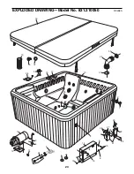
Page 23: ...1 2 2 3 4 5 6 9 10 12 13 14 15 16 17 18 32 31 29 30 25 26 11 8 19 19 8 8 7 28 21 27 33 3 23 23 22 20 25 34 37 36 35 24 19 EXPLODED DRAWINGÑModel No 831 210050 R0498A 23 ...

Page 24: ...e to you CUSTOMER HOT LINE 1 800 999 3756 Mon ÐFri 6 a m Ð6 p m MST ORDERING REPLACEMENT PARTS To order replacement parts simply call our Customer Service Department toll free at 1 800 999 3756 Monday through Friday 6 a m until 6 p m Mountain Time excluding holidays To help us assist you please be prepared to give the following information when calling 1 The MODEL NUMBER of the product 831 210050 ...

Reviews: