background image

10

MAINTENANCE 

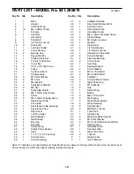
CONSOLE TROUBLE-SHOOTING

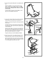
If the console does not function properly, the batteries
should be replaced. To replace the batteries, see
assembly step 10 on page 8. In addition, make sure
that the console wire is connected to the seat bar
wire. See assembly step 5 on page 6. 

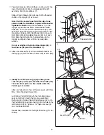
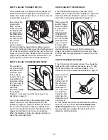
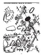
HOW TO REMOVE THE SIDE SHIELDS

For all of the following steps, one or both Side
Shields (11 and 27) must be removed. 

To remove the Left Side Shield (11), unscrew the 1/2Ó
Nylon Locknut (9) and remove the Pedal Bolt (8) and
the Plastic Pedal Spacer (42) from the Left Pedal Leg
(3). Unscrew the seven M4 x 38mm Screws (4) from
the Left Side Shield. Gently pull the Left Side Shield
out and to the side, so the Crank Arm (10) fits
through the hole in the Side Shield.

To remove the Right Side Shield (27), first remove the
Left Side Shield (11) as described above. Then

unscrew the three M4 x 38mm Screws (4) from the
lower edge of the Right Side Shield. Remove the 1/2Ó
Nylon Locknut (9), Pedal Bolt (8) and Plastic pedal
Spacer (42) from the Right Pedal Leg (70, not shown).
Gently pull the Right Side Shield over the Crank Arm.

11

9

4

8

42

4

10

3

4

4

27

4

which mode is
currently dis-
played. Note: If
a different
mode is select-
ed, you can
select the scan
mode again by
repeatedly
pressing the mode button.

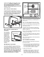
Speed, time, distance, fat calorie or calorie
mode

ÑTo select one of these modes for continu-

ous display, press the mode button repeatedly. The
mode indicators will show which mode is selected.
(Make sure that the scan mode is not selected.)   

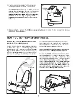
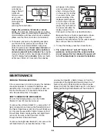
3. To measure your pulse, stop pedaling and place

your thumb on the pulse sensor as shown. The
pulse sensor is pressure-activatedÑfully press
down the pulse sensor. 

Do not press too hard, or

the circulation in your thumb will be restricted,
and your pulse will not be detected.

Next, slightly

raise your thumb until the heart-shaped indicator in
the LCD display flashes 

steadily

. Hold your thumb

at this level. After 5 to 10 seconds, three dashes

will appear in the display
and your pulse will be
shown. Hold your thumb
on the sensor for another
15 seconds for the most
accurate reading. If the
displayed pulse appears
to be too high or too low,
or if your pulse is not dis-
played, lift your thumb off
the sensor and allow the
display to reset. Press
down again on the sensor as described above. 

Make sure that your thumb is positioned as shown,
and that you are applying the proper amount of
pressure to the pulse sensor. Try the sensor several
times until you become familiar with it. 

4. To reset the display, press the on/reset button.

5.

The console has an Òauto-offÓ feature. If the
pedals are not moved and the console buttons
are not pressed for four minutes, the power will
turn off automatically to conserve the batteries. 

Mode Indicators

Summary of Contents for 831.285870

Page 1: ...831 285870 Serial No Write the serial number in the space above for reference CAUTION Read all precautions and instruc tions in this manual before using this equipment Save this manual for future refe...

Page 2: ...than 250 pounds 7 Wear appropriate exercise clothing when using the REBEL Always wear athletic shoes for foot protection 8 Always hold the handlebars when mounting dismounting and using the REBEL Step...

Page 3: ...1 800 736 6879 Monday through Saturday 7 a m until 7 p m Central Time excluding holidays To help us assist you please note the product model number and serial number before calling The model number is...

Page 4: ...rts may have been pre attached for shipping If a part is not in the parts bag check to see if it has been pre attached M10 Nylon Locknut 54 6 1 2 Nylon Locknut 9 2 Pedal Bolt 8 2 M10 x 68mm Bolt 67 4...

Page 5: ...the unit on its side ASSEMBLY Assembly requires two persons Place all parts of the PROFORM REBEL in a cleared area and remove the packing materials Do not dispose of the packing materials until assemb...

Page 6: ...ft into the indicated hole in the Seat Bar 6 Slide the Detent Ring 73 onto the console shaft and line up the hole in the Ring with the hole in the shaft Secure the Console 5 with the Console Mount Scr...

Page 7: ...9 36 Lock Pin 90 Lubricate 7 Plug the Extension Wire 49 that is coming out of the top of the Upright 2 into the Handlebar Wire 87 extending from the Handlebar 7 Slide a Plastic Sleeve 53 onto each of...

Page 8: ...osition Next step onto the other pedal Push the pedals until they begin to move with a continuous motion Note The crank can turn in either direc tion To get the full impact of the elliptical motion it...

Page 9: ...play are described below Note Before the con sole can be operated two AA batteries must be installed see assembly step 10 on page 8 Speed This mode displays your pedaling speed in miles per hour Time...

Page 10: ...ime distance fat calorie or calorie mode To select one of these modes for continu ous display press the mode button repeatedly The mode indicators will show which mode is selected Make sure that the s...

Page 11: ...Flywheel 20 to make sure that there is not too much resistance When the Resistance Strap is properly adjusted re attach the Left Side Shield HOW TO ADJUST THE DRIVE BELT If the Drive Belt 32 slips as...

Page 12: ...per intensity level for a sustained period of time During the first few minutes of exercise your body uses easi ly accessible carbohydrate calories for energy Only after the first few minutes does you...

Page 13: ...on the floor Bend your front leg lean for ward and move your hips toward the wall Hold for 15 counts then relax Repeat 3 times for each leg To cause further stretching of the achilles tendons bend you...

Page 14: ...ushing 40 1 Backrest 41 1 Small Spring 42 2 Plastic Pedal Spacer 43 1 Seat 44 2 1 1 2 x 2 1 2 Inner Cap 45 1 Console Axle 46 1 Console Spring Key No Qty Description 47 4 Stabilizer Endcap 48 1 Reed Sw...

Page 15: ...3 24 25 26 55 65 65 66 54 54 68 44 44 62 18 62 64 50 67 30 70 4 4 27 33 41 33 34 2 54 31 67 54 40 72 72 6 7 28 43 83 85 63 69 73 46 60 45 5 30 30 28 35 37 38 38 4 4 4 4 81 42 42 52 74 84 84 71 71 82 6...

Page 16: ...ter To request service or to order parts by telephone call the toll free numbers listed at the left When requesting help or service or ordering parts please be prepared to provide the following inform...

Reviews: