background image

21

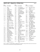
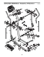
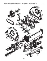
Note: “#” indicates a non-illustrated part. Specifications are subject to change without notice. See the back cover

of this manual for information about ordering replacement parts. 

1

1

Base

2

1

Frame

3

1

Upright

4

1

Console Bracket

5

1

Console

6

1

Front Stabilizer

7

1

Rear Stabilizer

8

1

Left Handlebar

9

1

Right Handlebar

10

2

Handlebar Endcap

11

1

Left Upper Body Arm

12

1

Right Upper Body Arm

13

1

Left Pedal

14

1

Left Pedal Leg

15

1

Right Pedal

16

1

Right Pedal Leg

17

2

Upright Cover

18

1

Left Front Handlebar

Cover

19

1

Left Rear Handlebar

Cover

20

1

Right Front Handlebar

Cover

21

1

Right Rear Handlebar

Cover

22

1

Water Bottle Holder

23

2

Front Stabilizer Endcap

24

2

Rear Stabilizer Endcap

25

2

Wheel

26

1

Base Foot

27

2

Leveling Foot

28

1

Left Side Shield

29

1

Right Side Shield

30

6

Upper Body Bushing

31

4

Pedal Leg Cover

32

2

Pedal Leg Axle

33

4

Pedal Leg Bushing

34

1

Base Axle

35

2

Base Bushing

36

2

Crank Arm

37

2

Inner Crank Cover

38

2

Crank Hub

39

1

Pulley Spacer

40

1

Pulley

41

2

Crank Bushing Cover

42

4

Crank Bushing

43

2

Crank Bushing Sleeve

44

2

Crank Bearing Set

45

1

Crank

46

1

Crank Spacer

47

2

Crank Snap Ring

48

1

Upper Wire Harness

49

1

Lower Wire Harness

50

1

Reed Switch/Wire

51

1

Belt

52

1

Flywheel

53

1

“C” Magnet

54

1

Pillow Block

55

1

Magnet

56

1

Spring

57

1

Idler

58

1

Idler Bracket

59

1

Clamp

60

1

Reed Switch Bracket

61

1

Base Pin

62

2

Latch Bracket Spacer

63

2

Hair Pin

64

1

Latch Bracket

65

1

Pivot Bracket

66

2

Pivot Bracket Spacer

67

1

Frame Pin

68

1

Latch Button

69

1

Roll Pin

70

1

Motor

71

1

Resistance Cable Pulley

72

1

Resistance Cable Set

73

2

Foam Grip

74

1

Pivot Axle

75

2

Hub Cover

76

2

Outer Crank Cover

77

4

M6 x 20mm Button

Screw

78

4

M8 x 43mm Button Bolt

79

7

M8 Jamnut

80

1

M8 x 69mm Button Bolt

81

4

M10 Nylon Locknut

82

2

M10 x 80mm Carriage

Bolt

83

2

M10 x 127mm Button

Screw

84

6

M8 x 23mm Button

Screw

85

1

M6 x 10mm Button

Screw

86

2

Crank Screw

87

8

Hub Screw

88 10

M8 Washer

89

2

M10 x 60mm Button

Screw

90

3

M8 Split Washer

91

1

Flywheel Spacer

92

1

Flywheel Washer

93

1

Flywheel Snap Ring

94

4

Pillow Block Screw

95

1

Stop Screw

96

1

M8 x 35mm Screw

97

1

“E” Clip

98

4

Pulley Screw

99

2

Crank Washer

100 2

M4 x 25mm Screw

101 8

M4 x 16mm Round

Head Screw

102 4

Motor Washer

103 27

M4 x 16mm Screw

104 8

M4 x 14mm Screw

105 6

M4 x 32mm Round

Head Screw

106 2

M8 x 31mm Shoulder

Screw

107 4

M4 x 12mm Screw

108 2

M4 x 45mm Screw

109 2

Large Wave Washer

110 2

M8 Small Washer

111 2

Wave Washer

112 8

Star Washer

113 1

M10 Washer

114 1

M6 Nut

115 4

M8 x 23mm Shoulder

Screw

116 2

Flywheel Bracket

#

2

Allen Wrench

#

1

Grease

#

1

User’s Manual

Key

No. Qty. Description

Key

No. Qty. Description

Key

No. Qty. Description

PART LIST—Model No. PFEL5105.0

R0805A

Summary of Contents for 850 Elliptical

Page 1: ...IONS As a manufacturer we are com mitted to providing complete customer satisfaction If you have questions or if parts are damaged or missing PLEASE CONTACT OUR CUSTOMER SERVICE DEPARTMENT DIRECTLY CA...

Page 2: ...SEMBLY 5 HOW TO USE THE ELLIPTICAL EXERCISER 10 MAINTENANCE AND TROUBLESHOOTING 18 CONDITIONING GUIDELINES 19 PART LIST 21 EXPLODED DRAWING 22 HOW TO ORDER REPLACEMENT PARTS Back Cover LIMITED WARRANT...

Page 3: ...g more than 250 pounds 8 Wear appropriate exercise clothes when using the elliptical exerciser Always wear athletic shoes for foot protection while exer cising 9 Hold the handgrip pulse sensor or the...

Page 4: ...lp us assist you please note the product model number and serial number before call ing The model number is PFEL5105 0 The serial number can be found on a decal attached to the ellip tical exerciser s...

Page 5: ...s The number in parentheses below each drawing is the key number of the part from the PART LIST on page 21 The second number is the quantity needed for assembly Note Some small parts may have been pre...

Page 6: ...s resting on the floor 4 Hold a Hub Cover 75 and a Crank Arm 36 against the left Crank Hub 38 Align the holes in the Hub Cover and the Crank Arm with the unused holes in the left Crank Hub Next insert...

Page 7: ...e two tabs on the battery cover and remove the bat tery cover Next insert four batteries into the Console Make sure that the batteries are oriented as shown by the diagrams inside of the battery compa...

Page 8: ...end of the Pivot Axle Tighten an M8 x 23mm Button Screw 84 with an M8 Washer 88 and a Wave Washer 111 into each end of the Pivot Axle 74 Make sure that the Wave Washers are on the ends of the Pivot A...

Page 9: ...Pedal Leg 14 and set the Left Pedal Leg on the left Crank Bushing Sleeve 43 Release the lever and make sure that the Left Pedal Leg is securely connected to the Crank Bushing Sleeve Connect the Right...

Page 10: ...al legs on the sleeves on the crank arms Release the latches and make sure that the pedal legs are securely connected to the crank arms HOW TO MOVE THE ELLIPTICAL EXERCISER To move the elliptical exer...

Page 11: ...tion It is recommended that you turn the crank arms in the direction shown by the arrow at the right how ever for variety you can turn the crank arms in the opposite direction To dismount the elliptic...

Page 12: ...even monitor your heart rate using the handgrip pulse sen sor The console also offers two pulse control programs and six resistance rpm programs Each pulse control pro gram automatically controls the...

Page 13: ...he pedals to reach the selected resistance level Monitor your progress with the display The left side of the display The left side of the display will show the elapsed time and the approximate number...

Page 14: ...your heart rate is not shown make sure that your hands are positioned as described Be care ful not to move your hands excessively or to squeeze the metal contacts too tightly For opti mal performance...

Page 15: ...ate setting see EXERCISE INTENSI TY on page 19 Hold the handgrip pulse sensor It is not necessary to hold the handgrip pulse sensor continuously during a pulse control pro gram however you should hold...

Page 16: ...t pace Important The Pace Coach is intended only to provide a goal Make sure to pedal at a pace that is comfortable for you Note During the program you can manually over ride the resistance setting if...

Page 17: ...ed only to provide motivation Your actual pace may be slower than the pace settings Make sure to exercise at a pace that is comfortable for you When only three seconds remain in the first seg ment of...

Page 18: ...ing feet beneath the rear stabilizer until the rocking motion is eliminated HANDGRIP PULSE SENSOR TROUBLESHOOTING Avoid moving your hands while using the handgrip pulse sensor Excessive movement may i...

Page 19: ...strengthen your cardiovascular sys tem your exercise must be aerobic Aerobic exer cise is activity that requires large amounts of oxygen for prolonged periods of time This increases the demand on the...

Page 20: ...Stretch With one leg in front of the other reach forward and place your hands against a wall Keep your back leg straight and your back foot flat on the floor Bend your front leg lean forward and move...

Page 21: ...llow Block 55 1 Magnet 56 1 Spring 57 1 Idler 58 1 Idler Bracket 59 1 Clamp 60 1 Reed Switch Bracket 61 1 Base Pin 62 2 Latch Bracket Spacer 63 2 Hair Pin 64 1 Latch Bracket 65 1 Pivot Bracket 66 2 Pi...

Page 22: ...20 21 22 23 23 25 25 26 30 30 30 30 30 30 31 31 32 33 33 31 33 32 33 31 34 35 35 80 78 101 101 79 105 105 88 84 79 77 77 101 101 84 101 101 74 105 79 78 88 84 104 115 115 104 88 84 104 115 115 104 10...

Page 23: ...6 36 75 37 83 87 87 76 103 103 103 103 86 99 44 98 98 44 45 46 47 47 103 100 103 51 50 52 53 54 55 56 94 94 94 79 92 93 91 57 58 59 60 103 103 85 96 61 62 62 63 64 63 65 66 67 68 69 113 97 70 95 103 7...

Page 24: ...does not extend to any product or damage to a product caused by or attributable to freight damage abuse misuse improper or abnormal usage or repairs not provided by an ICON authorized service center...

Reviews: