

20
Inspect and tighten all parts of the elliptical crosstrainer
regularly. Replace any worn parts immediately.
To clean the elliptical crosstrainer, use a damp cloth
and a small amount of mild dish soap. Important:
Keep liquids away from the console and keep the
console out of direct sunlight. During storage,
remove the batteries from the console.
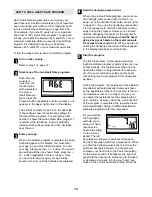
BATTERY REPLACEMENT
If the console display becomes dim, the batteries
should be replaced. Refer to assembly step 5 on
page 6 for replacement instructions.
HANDGRIP PULSE SENSOR TROUBLE-SHOOTING
• Avoid moving your hands while using the handgrip
pulse sensor; excessive movement may interfere
with heart rate readings. Do not hold the metal con-
tacts too tightly.
• For the most accurate heart rate reading, hold the
metal contacts for about 15 seconds.
• For optimal performance of the handgrip pulse sen-
sor, clean the metal contacts with a soft cloth—do
not use alcohol, abrasives, or chemicals.
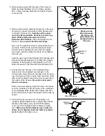
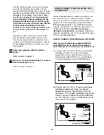
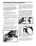
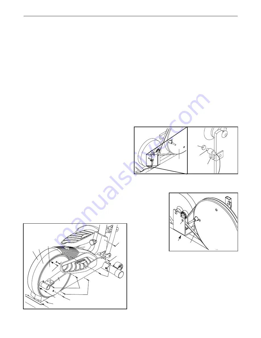
HOW TO ADJUST THE REED SWITCH
If the console does not display correct feedback, the
reed switch should be adjusted. To do this, you must
remove the Pedal Springs (11), the right Pedal Disc
(15), and the Side Shields (3, 4). Refer to step 9 on
page 8 and remove the Pedal Springs.
Next, remove the four Screws (51) from the right
Pedal Disc (15), and slide the Pedal Disc off. Remove
all Screws (52, 64) from the Right Side Shield (4) and
the two Screws (77) from beneath the Pedal Disc, and
remove the Right Side Shield (4). Remove all Screws
(52) from the Left Side Shield (3) and remove the Left
Side Shield.
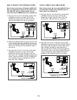
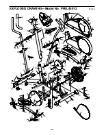
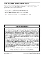
Next, refer to the drawing below and locate the Reed
Switch (53). Loosen, but do not remove, the indicated
M4 x 16mm Self-tapping Screw (52). Slide the Reed
Switch slightly toward or away from the Magnet (58) on
the flywheel. Retighten the Screw. Turn the left Pedal
Disc (15) for a moment. Repeat until the console dis-
plays correct feedback. When the Reed Switch is cor-
rectly adjusted, reattach the Side Shields (3, 4), the
right Pedal Disc (15), and the Pedal Springs (11).
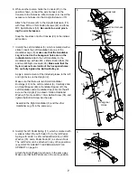
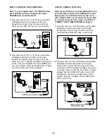
HOW TO ADJUST THE DRIVE BELT
If you can feel
the pedals slip
while you are
pedaling, even
when the
resistance is
adjusted to
the highest
level, the
Drive Belt (19)
may need to
be adjusted.
To adjust the
Drive Belt, you must first remove both side shields.
Refer to HOW TO ADJUST THE REED SWITCH at
the left and remove the side shields.
Next, loosen the M8 x 22mm Flat Head Screw (68)
and turn the M10 x 70mm Bolt (62) until the Drive Belt
(19) is tight. When the Drive Belt is tight, tighten the
Flat Head Screw. Reattach the side shields.
MAINTENANCE AND TROUBLESHOOTING
64
77
51
51
51
77
52
52
64
64
11
11
4
15
3
58
53
52
15
68
62
19


