background image

22

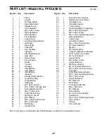
Note: # indicates a non-illustrated part. Specifications are subject to change without notice. 

1

1

Frame

2

1

Upright

3

1

Left Side Shield

4

1

Right Side Shield

52

Handlebar Leg

6

1

Left Handlebar

7

1

M6 x 25mm Screw

8

1

Right Handlebar

9

1

Rear Stabilizer

10

1

Front Stabilizer

11

2

Pedal Spring

12

1

Left Rear Spring Bracket

13

1

Left Pedal

14

1

Right Pedal

152

Pedal Disc

16

2

Disc Crossbar

17

1

Flywheel

18

1

Side Shield Bracket

19

1

Drive Belt

20

2

Rear Endcap

21

2

Front Endcap

22

2

Wheel

23

1

Console

24

2

Handgrip

251

Idler Bracket

26

2

Idler Washer

27

2

Idler Bearing

28

1

Idler Axle

29

1

Handgrip Pulse Sensor

30

2

Large Snap Ring

31

2

Large Bearing

32

1

Pedal Axle

33

5M10 Nylon Locknut

34

4

M10 x 75mm Carriage Bolt

352

Spring Bracket Washer

36

12

M6 x 33.5mm Bolt

37

4

Pedal Arm Bushing

38

5M8 Nylon Locknut

39

2

M10 Washer

40

2

M10 x 27mm Patch Screw

41

2

M6 x 72mm Bolt

42

4

M5 Washer

43

1

Upright Knob

44

1

Extension Wire Harness

451

Resistance Control Motor

46

2

Handlebar Cap

47

2

Handlebar Spacer

48

2

Frame Spacer

49

4

Small Handlebar Arm Bushing 

50

4

M8 x 45mm Button Bolt

51

8

M6 x 30mm Screw

52

12

M4 x 16mm Self-tapping Screw

53

1

Reed Switch/Wire

54

1

Cable Clamp

55

2

Handlebar Washer

56

2

M8 x 19mm Button Screw

57

1

M10 Flat Head Bolt

58

1

Magnet

59

6

M10 Split Washer

60

4

Large Handlebar Arm Bushing

61

2

5/16” x 25.4mm Hex Bolt

62

1

M10 x 70mm Bolt

63

2

Spring Spacer

64

4

M4 x 25mm Screw

651

Upright Bushing

66

16

M6 Nylon Locknut

67

6

M10 x 27mm Button Screw

68

1

M8 x 22mm Flat Head Screw

69

1

Push Nut

70

1

Right Rear Spring Bracket

71

2

M5 x 16mm Self-tapping Screw

72

2

M5 x 12mm Screw

73

1

Upright Extension

74

2

M10 Bolt Set

7512

M6 Washer

76

2

Front Spring Bracket

77

2

M6 x 18mm Bolt

78

5M10 Washer

79

1

Wire Harness

80

2

M10 x 27mm Pedal Bolt

81

2

Pedal Knob

82

2

M5 x 14mm Self-tapping Screw

#

1

Allen Wrench

#

1

Grease

#

1

User’s Manual

Key No. Qty.

Description

Key No. Qty.

Description

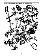
PART LIST—Model No. PFEL45012

R1102A

Summary of Contents for 900 Cardiocross Trainer Elliptical

Page 1: ...parts we will guar antee complete satisfaction through direct assistance from our factory TO AVOID UNNECESSARY DELAYS PLEASE CALL DIRECT TO OUR TOLL FREE CUSTOMER HOT LINE The trained techni cians on...

Page 2: ...5 HOW TO USE THE ELLIPTICAL CROSSTRAINER 9 MAINTENANCE AND TROUBLESHOOTING 20 CONDITIONING GUIDELINES 21 PART LIST 22 EXPLODED DRAWING 23 HOW TO ORDER REPLACEMENT PARTS Back Cover LIMITED WARRANTY Bac...

Page 3: ...letic shoes for foot protection 8 Always hold the handgrip pulse sensor or the handlebars when mounting dismounting or using the elliptical crosstrainer 9 The pulse sensor is not a medical device Vari...

Page 4: ...OFORM 900 If you have additional questions please call our Customer Service Department toll free at 1 800 999 3756 Monday through Friday 6 a m until 6 p m Mountain Time excluding holidays To help us a...

Page 5: ...small parts may have been pre assembled for shipping If a part is not in the parts bag check to see if it has been pre assembled M4 x 16mm Screw 52 2 M10 x 27mm Screw 67 6 M10 Washer 78 2 M10 Split W...

Page 6: ...gh the Upright Extension 73 Attach the Upright Extension to the Upright 2 with three M10 x 27mm Button Screws 67 and three M10 Split Washers 59 4 Connect the wire harness on the Handgrip Pulse Sensor...

Page 7: ...Do not fully tighten the Button Bolts yet Apply a small amount of the included grease to the left and right axles on the Upright 2 Make sure that there are two Small Handlebar Bushings 49 in the Left...

Page 8: ...s completed To protect the floor or carpet from damage place a mat under the elliptical crosstrainer B 23 Jack 23 Lift Here 1 A Cylinder 2 9 Apply a small amount of grease to the axle on the left Disc...

Page 9: ...O EXERCISE ON THE ELLIPTICAL CROSSTRAINER To mount the elliptical cross trainer hold the handgrip pulse sensor and step onto the pedal that is in the lowest position Then step onto the other pedal Pus...

Page 10: ...T com interactive technology IFIT com technology is like having a per sonal trainer right in your home Using a stereo audio cable available at electronics stores you can connect the elliptical crosstr...

Page 11: ...mode indicators These indicators show which feedback mode scan speed time distance resistance level calories fat calories or heart rate is currently shown Note When the distance is shown the word Mil...

Page 12: ...m instead of the elapsed time In addition the left bar graph will appear in the dis play to show your exercise pace As you increase or decrease your pace additional bars will appear or disappear on th...

Page 13: ...of the program is completed the resistance level will automatically change if a different resistance setting is programmed for the next period The pace set tings for the pro gram will be shown by the...

Page 14: ...r to step 5 on page 12 or the optional chest pulse sensor refer to page 19 If you use the handgrip pulse sensor it is not necessary to hold the handgrips continu ously during the program However you s...

Page 15: ...nnected to your portable CD player portable stereo home stereo or computer with CD player See pages 15 to 17 for connecting instructions To use iFIT com videocassettes the elliptical crosstrainer must...

Page 16: ...to the PHONES jack on your stereo Plug your headphones into the other side of the Y adapter HOW TO CONNECT YOUR HOME STEREO Note If your stereo has an unused LINE OUT jack see instruction A below If t...

Page 17: ...see instruction B If you have a TV with a built in VCR see instruction B If your VCR is connected to your home stereo see HOW TO CONNECT YOUR HOME STEREO on page 16 A Plug one end of a 1 8 to RCA ste...

Page 18: ...ay button on your CD player or VCR A moment after the play button is pressed your personal trainer will begin guiding you through your workout Simply follow your personal trainer s instructions The pr...

Page 19: ...necessary and go to our Web site at www iFIT com Follow the desired links on our Web site to select a program Read and follow the on line instructions for using a program Follow the on line instructio...

Page 20: ...prings Next remove the four Screws 51 from the right Pedal Disc 15 and slide the Pedal Disc off Remove all Screws 52 64 from the Right Side Shield 4 and the two Screws 77 from beneath the Pedal Disc a...

Page 21: ...is to strengthen your cardiovascular sys tem your exercise must be aerobic Aerobic exer cise is activity that requires large amounts of oxygen for prolonged periods of time This increases the demand o...

Page 22: ...m Bolt 42 4 M5 Washer 43 1 Upright Knob 44 1 Extension Wire Harness 45 1 Resistance Control Motor 46 2 Handlebar Cap 47 2 Handlebar Spacer 48 2 Frame Spacer 49 4 Small Handlebar Arm Bushing 50 4 M8 x...

Page 23: ...1 34 9 33 33 20 20 16 61 54 52 53 26 38 28 25 68 27 69 62 55 56 38 50 48 47 49 24 56 55 57 39 39 33 58 22 41 21 66 41 21 22 37 66 34 81 78 80 81 78 80 60 60 60 23 52 52 64 52 77 52 77 64 37 37 49 48 4...

Page 24: ...must be pre authorized by ICON This warranty does not extend to any product or damage to a product caused by or attributable to freight damage abuse misuse improper or abnormal usage or repairs not p...

Reviews: