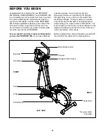
background image

6

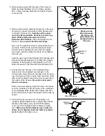
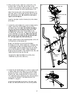
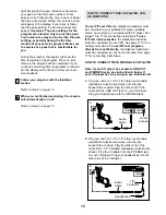
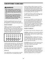
2. While another person lifts the back of the Frame (1),

attach the Rear Stabilizer (9) to the Frame with two
M10 x 75mm Carriage Bolts (34) and two M10 Nylon
Locknuts (33). 

34

9

1

3

2

43

44

1

73

79

59

Adjustment

Holes

Make sure the

Wire Harnesses

(44, 79) do not

get pinched and

damaged during

this step.

44

67

67

59

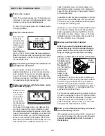
3. While another person holds the Upright (2) in the posi-

tion shown, connect the Extension Wire Harness (44)
to the Wire Harness (79). Carefully pull the upper
end of the Extension Wire Harness to remove any
slack. While holding the upper end of the
Extension Wire Harness, 
insert the Upright into the
Frame (1). Do not pinch the Wire Harnesses.

Next, turn the Upright Knob (43) counterclockwise sev-
eral turns. Pull the Knob, slide the Upright (2) down
until the Knob is aligned with one of the four adjust-
ment holes, and then release the Knob. Do not tighten
the Knob yet.

Feed the upper end of the Extension Wire Harness (44)
through the Upright Extension (73). Attach the Upright
Extension to the Upright (2) with three M10 x 27mm
Button Screws (67) and three M10 Split Washers (59).

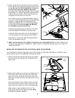
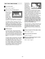
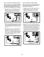
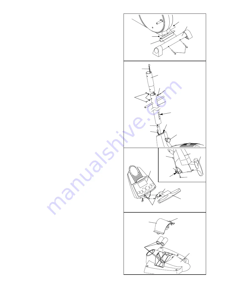
4. Connect the wire harness on the Handgrip Pulse

Sensor (29) to the indicated wire harness on the
Console (23). Insert both wire harnesses into the open-
ing in the bottom of the Console. Next, insert the metal
tube on the Handgrip Pulse Sensor into the opening in
the bottom of the Console. Be careful not to pinch
the wire harnesses.

Refer to the inset drawing. Align the holes in the brack-
et on the Console (23) with the holes in the metal tube
on the Handgrip Pulse Sensor (29). Tighten two M4 x
16mm Screws (52) through the bracket into the tube as
shown.   

29

23

Wire Harnesses

4

2

33

33

Tube

52

23

Bracket

29

52

Tube

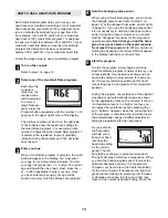
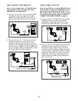
5. The Console (23) requires four “D” batteries (not

included); alkaline batteries are recommended. Press
the tab on the battery cover, and lift off the battery
cover. Insert four batteries into the battery compart-
ment. Make sure that the batteries are oriented as
shown by the diagram inside the battery compart-
ment. 
Reattach the battery cover. 

23

Tab

Batteries

Battery

Cover

5

Summary of Contents for 900 Cardiocross Trainer Elliptical

Page 1: ...parts we will guar antee complete satisfaction through direct assistance from our factory TO AVOID UNNECESSARY DELAYS PLEASE CALL DIRECT TO OUR TOLL FREE CUSTOMER HOT LINE The trained techni cians on...

Page 2: ...5 HOW TO USE THE ELLIPTICAL CROSSTRAINER 9 MAINTENANCE AND TROUBLESHOOTING 20 CONDITIONING GUIDELINES 21 PART LIST 22 EXPLODED DRAWING 23 HOW TO ORDER REPLACEMENT PARTS Back Cover LIMITED WARRANTY Bac...

Page 3: ...letic shoes for foot protection 8 Always hold the handgrip pulse sensor or the handlebars when mounting dismounting or using the elliptical crosstrainer 9 The pulse sensor is not a medical device Vari...

Page 4: ...OFORM 900 If you have additional questions please call our Customer Service Department toll free at 1 800 999 3756 Monday through Friday 6 a m until 6 p m Mountain Time excluding holidays To help us a...

Page 5: ...small parts may have been pre assembled for shipping If a part is not in the parts bag check to see if it has been pre assembled M4 x 16mm Screw 52 2 M10 x 27mm Screw 67 6 M10 Washer 78 2 M10 Split W...

Page 6: ...gh the Upright Extension 73 Attach the Upright Extension to the Upright 2 with three M10 x 27mm Button Screws 67 and three M10 Split Washers 59 4 Connect the wire harness on the Handgrip Pulse Sensor...

Page 7: ...Do not fully tighten the Button Bolts yet Apply a small amount of the included grease to the left and right axles on the Upright 2 Make sure that there are two Small Handlebar Bushings 49 in the Left...

Page 8: ...s completed To protect the floor or carpet from damage place a mat under the elliptical crosstrainer B 23 Jack 23 Lift Here 1 A Cylinder 2 9 Apply a small amount of grease to the axle on the left Disc...

Page 9: ...O EXERCISE ON THE ELLIPTICAL CROSSTRAINER To mount the elliptical cross trainer hold the handgrip pulse sensor and step onto the pedal that is in the lowest position Then step onto the other pedal Pus...

Page 10: ...T com interactive technology IFIT com technology is like having a per sonal trainer right in your home Using a stereo audio cable available at electronics stores you can connect the elliptical crosstr...

Page 11: ...mode indicators These indicators show which feedback mode scan speed time distance resistance level calories fat calories or heart rate is currently shown Note When the distance is shown the word Mil...

Page 12: ...m instead of the elapsed time In addition the left bar graph will appear in the dis play to show your exercise pace As you increase or decrease your pace additional bars will appear or disappear on th...

Page 13: ...of the program is completed the resistance level will automatically change if a different resistance setting is programmed for the next period The pace set tings for the pro gram will be shown by the...

Page 14: ...r to step 5 on page 12 or the optional chest pulse sensor refer to page 19 If you use the handgrip pulse sensor it is not necessary to hold the handgrips continu ously during the program However you s...

Page 15: ...nnected to your portable CD player portable stereo home stereo or computer with CD player See pages 15 to 17 for connecting instructions To use iFIT com videocassettes the elliptical crosstrainer must...

Page 16: ...to the PHONES jack on your stereo Plug your headphones into the other side of the Y adapter HOW TO CONNECT YOUR HOME STEREO Note If your stereo has an unused LINE OUT jack see instruction A below If t...

Page 17: ...see instruction B If you have a TV with a built in VCR see instruction B If your VCR is connected to your home stereo see HOW TO CONNECT YOUR HOME STEREO on page 16 A Plug one end of a 1 8 to RCA ste...

Page 18: ...ay button on your CD player or VCR A moment after the play button is pressed your personal trainer will begin guiding you through your workout Simply follow your personal trainer s instructions The pr...

Page 19: ...necessary and go to our Web site at www iFIT com Follow the desired links on our Web site to select a program Read and follow the on line instructions for using a program Follow the on line instructio...

Page 20: ...prings Next remove the four Screws 51 from the right Pedal Disc 15 and slide the Pedal Disc off Remove all Screws 52 64 from the Right Side Shield 4 and the two Screws 77 from beneath the Pedal Disc a...

Page 21: ...is to strengthen your cardiovascular sys tem your exercise must be aerobic Aerobic exer cise is activity that requires large amounts of oxygen for prolonged periods of time This increases the demand o...

Page 22: ...m Bolt 42 4 M5 Washer 43 1 Upright Knob 44 1 Extension Wire Harness 45 1 Resistance Control Motor 46 2 Handlebar Cap 47 2 Handlebar Spacer 48 2 Frame Spacer 49 4 Small Handlebar Arm Bushing 50 4 M8 x...

Page 23: ...1 34 9 33 33 20 20 16 61 54 52 53 26 38 28 25 68 27 69 62 55 56 38 50 48 47 49 24 56 55 57 39 39 33 58 22 41 21 66 41 21 22 37 66 34 81 78 80 81 78 80 60 60 60 23 52 52 64 52 77 52 77 64 37 37 49 48 4...

Page 24: ...must be pre authorized by ICON This warranty does not extend to any product or damage to a product caused by or attributable to freight damage abuse misuse improper or abnormal usage or repairs not p...

Reviews: