background image

5

ASSEMBLY

To hire an authorized service technician to assemble the abdominal exerciser, call 1-800-445-2480.

Assembly requires two persons.

Place all parts of the abdominal exerciser in a cleared area and remove the

packing materials. Do not dispose of the packing materials until assembly is completed.

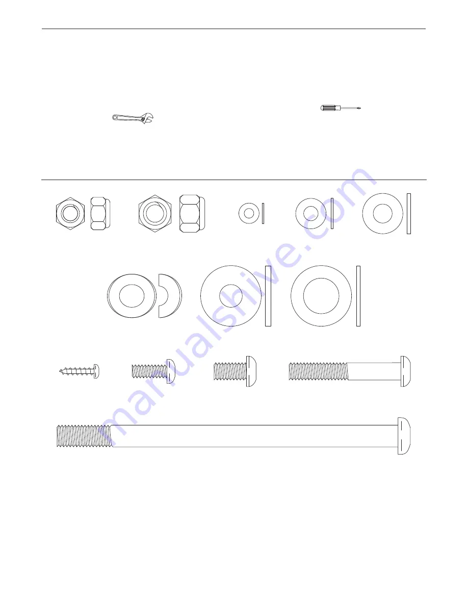
In addition to the included tool(s), assembly requires a Phillips screwdriver

and an

adjustable wrench

.

See the drawings below to identify the small parts needed for assembly. The number in parentheses below each

drawing is the key number of the part, from the PART LIST near the end of this manual. The number following

the key number is the quantity needed for assembly.

Note: If a part is not in the hardware kit, check to see if

it has been preassembled. To avoid damaging parts, do not use power tools for assembly.

M10 x 157mm Button Bolt (30)–1

Large Washer

(41)–1

Pivot Washer

(43)–1

M10 Curved

Washer (39)–2

M6 Washer

(35)–4

M10 Locknut

(38)–1

M8 Washer

(34)–13

M8 Locknut

(46)–1

M8 x 15mm Button

Screw (29)–12

M4 x 16mm

Screw (31)–2

M8 x 52mm Button

Bolt (47)–1

M6 x 16mm Button

Screw (28)–4

M4 Washer

(48)–2

Summary of Contents for ab glider

Page 1: ...lease contact Customer Care IMPORTANT Please register this product see the limited warranty on the back cover of this manual before contacting Customer Care CALL TOLL FREE 1 888 533 1333 Mon Fri 6 a m...

Page 2: ...5 ORDERING REPLACEMENT PARTS Back Cover LIMITED WARRANTY Back Cover WARNING DECAL PLACEMENT PROFORM is a registered trademark of ICON IP Inc This drawing shows the location s of the warning decal s If...

Page 3: ...nd dust Place the abdominal exerciser on a level surface with carpet or a non slip mat beneath it 6 Make sure that there is enough clearance around the abdominal exerciser to mount dismount and use th...

Page 4: ...our overall fitness For your benefit read this manual carefully before using the abdominal exerciser If you have ques tions after reading this manual please see the front cover of this manual To help...

Page 5: ...small parts needed for assembly The number in parentheses below each drawing is the key number of the part from the PART LIST near the end of this manual The number following the key number is the qua...

Page 6: ...he other Base not shown and the other Frame Foot not shown in the same way 2 Insert the Upright 4 into the Frame 1 Attach the Upright 4 with three M8 x 15mm Button Screws 29 and three M8 Washers 34 Do...

Page 7: ...ecure the Handlebar 5 with the Handlebar Knob 37 4 3 43 1 41 29 4 Using a small plastic bag to keep your hand clean apply a small amount of the included grease to both sides of a Pivot Washer 43 and t...

Page 8: ...e Pivot Frame 3 7 Move the Roller Carriage 6 to the position shown and align the indicated hole in the Roller Carriage with the corresponding hole not shown in the Pivot Frame 3 Insert the Pin 27 into...

Page 9: ...hold the Handlebar 5 firmly with both hands Place one knee on the Knee Pad 7 halfway between the front of the Knee Pad and the back of the Knee Pad Then place your other knee on the Knee Pad Always ho...

Page 10: ...ide to side but the knee pad will move forward and back ward To exercise use your core muscles to move the knee pad forward and backward With the pivot frame unlocked and the knee pad locked the pivot...

Page 11: ...ole Then reattach the battery door HOW TO USE THE CONSOLE Note Make sure that a battery is installed see HOW TO INSTALL A BATTERY at the left If there is a sheet of plastic on the display remove the p...

Page 12: ...rm aerobic exercise which is activity that requires large amounts of oxygen for prolonged periods of time For aerobic exercise adjust the intensity of your exercise until your heart rate is near the h...

Page 13: ...lles Stretch With one leg in front of the other reach forward and place your hands against a wall Keep your back leg straight and your back foot flat on the floor Bend your front leg lean forward and...

Page 14: ...Grip 18 2 Reed Switch 19 2 Upper Roller 20 2 Lower Roller 21 2 Roller Carriage Cap 22 1 Long Magnet Bracket 23 1 Short Magnet Bracket 24 3 Console Screw 25 4 Roller Spacer 26 1 M4 x 12mm Screw 27 1 P...

Page 15: ...25 25 25 27 28 29 26 29 29 29 29 31 31 10 31 31 31 32 32 32 32 31 31 31 50 31 31 33 38 30 36 36 36 36 35 35 20 44 44 38 40 40 41 29 8 44 44 43 37 28 31 39 39 45 34 34 34 34 34 24 24 36 36 20 45 34 47...

Page 16: ...mage to a product caused by or attributable to freight damage abuse misuse improper or abnormal usage or repairs not provided by an ICON authorized service center to products used for commercial or re...

Reviews: