background image

15

TROUBLESHOOTING

Most treadmill problems can be solved by following the steps below. Find the symptom that applies, and
follow the steps listed. If further assistance is needed, please call our Customer Service Department toll-
free at 1-888-533-1333, Monday through Friday, 6 a.m. until 6 p.m. Mountain Time (excluding holidays).

PROBLEM: The power does not turn on

SOLUTION:

a. Make sure that the power cord is plugged into a surge suppressor, and that the surge suppressor

is plugged into a properly grounded outlet (see page 10). Use only a single-outlet surge suppres-
sor that meets all of the specifications described on page 10. Important: The treadmill is not com-
patible with GFCI-equipped outlets.   

b. After the power cord has been plugged in, make sure that the key is fully inserted into the console.

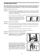
c. Check the reset/off circuit breaker located on the

treadmill frame near the power cord. If the switch
protrudes as shown, the circuit breaker has tripped.
To reset the circuit breaker, wait for five minutes
and then press the switch back in. 

PROBLEM: The power turns off during use

SOLUTION:

a. Check the circuit breaker located on the treadmill frame near the power cord (see the drawing

above). If the circuit breaker has tripped, wait for five minutes and then press the switch back in.

b. Make sure that the power cord is plugged in. If the power cord is plugged in, unplug it, wait for

five minutes, and then plug it back in.

c. Remove the key from the console. Reinsert the key fully into the console.

d. If the treadmill still will not run, please call our Customer Service Department.

PROBLEM: The displays of the console do not function properly

SOLUTION:

a. Remove the key from the console and 

UNPLUG THE

POWER CORD.

Remove the Screws (58) from the

Hood (1), and carefully pivot the Hood off.

Locate the Reed Switch (10) and the Magnet (18) on
the left side of the Pulley (17). Turn the Pulley until the
Magnet is aligned with the Reed Switch. 

Make sure

that the gap between the Magnet and the Reed
Switch is about 1/8”.

If necessary, loosen the Screw

(2), move the Reed Switch slightly, and then retighten
the Screw. Reattach the Hood, and run the treadmill
for a few minutes to check for a correct speed read-
ing.

Tripped

Reset

c

58

1

a

18

10

2

Top

View

1/8”

17

Summary of Contents for DTL33951

Page 1: ...e are missing or damaged parts we will guarantee complete sat isfaction through direct assis tance from our factory TO AVOID DELAYS PLEASE CALL DIRECT TO OUR TOLL FREE CUSTOMER HOT LINE The trained te...

Page 2: ...MENT 10 HOW TO FOLD AND MOVE THE TREADMILL 13 TROUBLESHOOTING 15 CONDITIONING GUIDELINES 17 ORDERING REPLACEMENT PARTS Back Cover LIMITED WARRANTY Back Cover Note An EXPLODED DRAWING and a PART LIST a...

Page 3: ...ocal electronics store 12 Failure to use a properly functioning surge suppressor could result in damage to the con trol system of the treadmill If the control sys tem is damaged the walking belt may c...

Page 4: ...d ser vice representative only 25 This treadmill is intended for in home use only Do not use this treadmill in a commer cial rental or institutional setting WARNING Before beginning this or any exerci...

Page 5: ...ent toll free at 1 888 533 1333 Monday through Friday 6 a m until 6 p m Mountain Time excluding holidays To help us assist you please note the product model number and serial number before calling The...

Page 6: ...aner Assembly requires the included allen wrenches and your own phillips screwdriver rubber mallet and adjustable wrench For help identifying the assembly hardware see the drawings below If a part is...

Page 7: ...the Left Handrail 71 as de scribed above Do not tighten the Bolt yet Note There is not a wire harness on the left side 42 Hole 72 37 37 71 69 Hole 2 3 With the help of another person carefully lower...

Page 8: ...s not slide easily and snap into place turn the connector and then insert it 72 47 5 6 4 Attach each Extension Leg 63 with two 1 Tek Screws 39 and a Thin Base Pad 67 as shown Attach the lower Tek Scre...

Page 9: ...round Wire 36 32 47 8 Press the Upright Wire 42 into the slot in the underside of the Console Base 47 in the indicated area Cover the Upright Wire with the Right Grip Plate 36 Be careful not to pinch...

Page 10: ...grounding provides a path of least resistance for electric current to reduce the risk of elec tric shock This product is equipped with a cord having an equipment grounding conductor and a grounding p...

Page 11: ...he walking belt will begin to move Hold the handrails and begin walking As you exercise change the speed of the walking belt as desired by pressing the Speed and buttons Each time a button is pressed...

Page 12: ...t of measurement hold down the Stop button while inserting the key into the console An E for English miles or an M for metric kilometers will appear in the Speed display Press the Speed button to chan...

Page 13: ...l until the storage latch closes over the catch Make sure that the storage latch is fully engaged over the catch To protect the floor or carpet from damage place a mat under the treadmill Keep the tre...

Page 14: ...to the left Pivot the treadmill down until the frame and foot rail are past the storage latch 2 Hold the treadmill firmly with both hands and lower the tread mill to the floor Do not drop the treadmil...

Page 15: ...ess the switch back in PROBLEM The power turns off during use SOLUTION a Check the circuit breaker located on the treadmill frame near the power cord see the drawing above If the circuit breaker has t...

Page 16: ...off center or slips when walked on SOLUTION a If the walking belt is off center first remove the key and UNPLUG THE POWER CORD If the walking belt has shifted to the left use the allen wrench to turn...

Page 17: ...be aerobic Aerobic exercise is activity that requires large amounts of oxygen for prolonged periods of time This increases the demand on the heart to pump blood to the muscles and on the lungs to oxyg...

Page 18: ...les Stretch With one leg in front of the other reach forward and place your hands against a wall Keep your back leg straight and your back foot flat on the floor Bend your front leg lean forward and m...

Page 19: ...19 NOTES...
Page 20: ...10 1 2 Screw 49 9 Hood Screw Endcap Screw 50 1 Key Clip 51 1 Incline Motor 52 1 Incline Bracket 53 1 Incline Motor Bolt lower 54 2 Incline Pivot Bolt 55 1 Motor Mount Bracket 56 1 Motor Controller Wir...

Page 21: ...57 51 54 13 62 63 64 32 66 58 89 77 68 85 65 42 67 70 15 94 41 49 11 22 22 56 71 35 33 3 4 5 6 7 8 9 55 20 58 30 42 75 58 61 58 61 26 26 59 37 37 48 47 46 67 36 34 88 76 76 50 52 43 1 49 49 13 54 13...

Page 22: ...of revenues or profits loss of enjoyment or use costs of removal or installation or other consequential damages of whatsoever nature Some states do not allow the exclusion or limitation of in cidenta...

Reviews: