background image

8

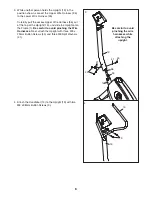
11.

Make sure that all parts are properly tightened before you use the exercise cycle. 

Note: After assembly is

completed, some extra parts may be left over. Place a mat beneath the exercise cycle to protect the floor. 

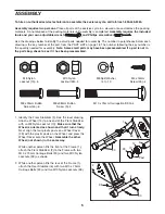
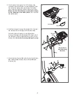
9. Attach the Seat (12) to the Seat Post (5) with four M8

Nylon Locknuts (10) and four M8 Split Washers (41).
Note: The Nylon Locknuts and the Split Washers may
be preattached to the underside of the Seat. 

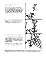
10. Identify the Left Pedal (24), which is marked with an

“L.” Using an adjustable wrench, 

firmly tighten

the

Left Pedal 

counterclockwise

into the left arm of the

Crank (21). Tighten the Right Pedal (not shown)

clockwise

into the right arm of the Crank. 

Important:

Tighten both Pedals as firmly as possible. After
using the exercise cycle for one week, retighten
the Pedals. For best performance, the Pedals must
be kept tightened.

Adjust the Left Pedal Strap (25) to the desired posi-
tion, and press the end of the Pedal Strap onto the
tab on the Left Pedal (24). Adjust the Right Pedal
Strap (not shown) in the same way. 

9

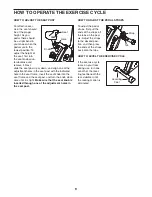
8. Turn the Seat Knob (11) counterclockwise and remove

it. Next, insert the Seat Post (5) into the Seat Frame
(28). Press the Seat Post Endcap (54) into the lower
end of the Seat Post. 

Next, align one of the adjustment holes in the Seat
Post (5) with the indicated hole in the Seat Frame (28).
Insert the Seat Knob (11) into the Seat Frame and the
Seat Post, and turn the Seat Knob clockwise until it is
tight. 

Make sure that the Seat Knob is inserted

through one of the adjustment holes in the Seat
Post.

28

5

11

54

Hole

Adjustment

Holes 

41

10

12

5

10

24

21

25

Tab

8

41

10

Summary of Contents for GR 75

Page 1: ...erial No QUESTIONS As a manufacturer we are com mitted to providing complete customer satisfaction If you have questions or if parts are damaged or missing PLEASE CONTACT OUR CUSTOMER SERVICE DEPARTME...

Page 2: ...ASSEMBLY 5 HOW TO OPERATE THE EXERCISE CYCLE 9 MAINTENANCE AND TROUBLESHOOTING 14 CONDITIONING GUIDELINES 15 PART LIST 18 EXPLODED DRAWING 19 HOW TO ORDER REPLACEMENT PARTS Back Cover LIMITED WARRANT...

Page 3: ...cise cycle do not arch your back 9 If you feel pain or dizziness while exercising stop immediately and cool down 10 The pulse sensor is not a medical device Various factors including the user s move m...

Page 4: ...see the front cover of this manual To help us assist you please note the product model number and serial number before contacting us The model number is PFEX1495 0 The serial number can be found on a...

Page 5: ...been preassembled M8 Nylon Locknut 10 6 M8 Split Washer 41 10 M10 Nylon Locknut 33 4 M4 x 16mm Screw 49 4 M8 x 25mm Button Screw 45 6 M10 x 75mm Carriage Bolt 30 4 M8 x 38mm Button Screw 9 2 1 Identi...

Page 6: ...re Harness 36 out of the top of the Upright 13 and slide the Upright onto the Frame 1 Be careful to avoid pinching the Wire Harnesses Next attach the Upright with three M8 x 25mm Button Screws 45 and...

Page 7: ...hing the wires 13 49 49 36 Console Wire 5 5 The Console 16 requires four D batteries not included alkaline batteries are recommended Press the tab on the battery door and remove the battery door Inser...

Page 8: ...as firmly as possible After using the exercise cycle for one week retighten the Pedals For best performance the Pedals must be kept tightened Adjust the Left Pedal Strap 25 to the desired posi tion a...

Page 9: ...Insert the seat knob into the seat frame and the seat post and turn the knob clock wise until it is tight Make sure that the seat knob is inserted through one of the adjustment holes in the seat post...

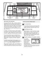
Page 10: ...pulse program see page 12 To use a preset program see page 13 Before using the console make sure that batteries are installed see assembly step 5 on page 7 If there is a sheet of clear plastic on the...

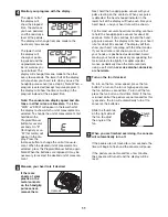
Page 11: ...he handgrip pulse sensor remove them Next hold the handgrip pulse sensor with your palms resting on the contacts When your pulse is detected the heart shaped indicator in the lower half of the display...

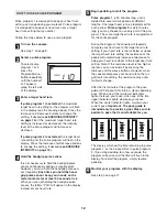
Page 12: ...ear in the display instead of your heart rate Begin pedaling to start the program Pulse program 1 is 30 minutes long and is divided into several time periods of different lengths One target heart rate...

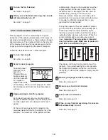
Page 13: ...display for a few seconds The resistance of the pedals will then automatically change to the resistance level that is programmed for the next period Note If the resistance level is too high or too low...

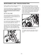
Page 14: ...d Turn the Crank 21 to the position shown Using an adjustable wrench turn the Left Pedal 24 clockwise and remove it Next remove the indicated M4 x 25mm Screws 42 and the indicated M4 x 16mm Screws 49...

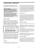
Page 15: ...u exercise Aerobic Exercise If your goal is to strengthen your cardiovascular sys tem your exercise must be aerobic Aerobic exer cise is activity that requires large amounts of oxygen for prolonged pe...

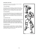
Page 16: ...le Hold for 15 counts then relax Repeat 3 times for each leg Stretches Hamstrings lower back and groin 3 Calf Achilles Stretch With one leg in front of the other reach forward and place your hands aga...

Page 17: ...17 NOTES...
Page 18: ...M10 Nylon Locknut 34 4 M5 Washer 35 2 Levelling Foot 36 1 Upper Wire Harness 37 1 Flywheel 38 1 Magnet 39 1 Right Pedal Strap 40 1 C magnet 41 10 M8 Split Washer 42 4 M4 x 25mm Screw 43 1 Reed Switch...

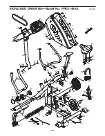
Page 19: ...6 37 40 43 44 6 48 19 30 30 33 33 33 49 41 42 49 49 34 45 45 45 41 41 41 27 38 21 55 53 7 49 49 42 41 10 47 34 28 9 20 11 56 56 52 52 56 54 41 45 45 41 45 41 23 23 14 31 47 35 35 50 32 10 42 49 42 46...

Page 20: ...t extend to any product or damage to a product caused by or attributable to freight damage abuse misuse improper or abnormal usage or repairs not provided by an ICON authorized service center products...

Reviews: