
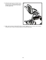


16
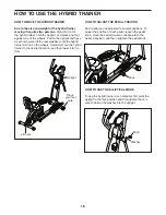
HOW TO USE THE HYBRID TRAINER
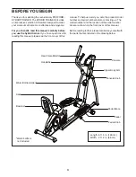
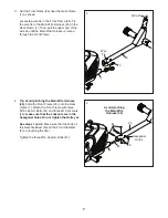
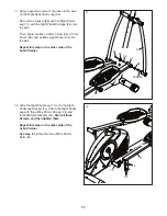
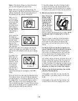
HOW TO MOVE THE HYBRID TRAINER
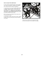
Due to the size and weight of the hybrid trainer,
moving it requires two persons.
Stand in front of
the hybrid trainer, hold the upright, and place one foot
against one of the wheels. Pull on the upright and have
a second person lift the rear stabilizer until the hybrid
trainer will roll on the wheels. Carefully move the hybrid
trainer to the desired location, and then lower it to the
floor.
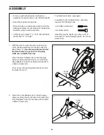
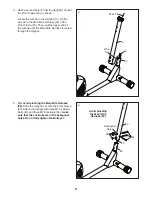
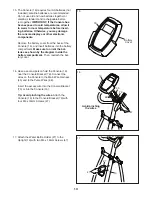
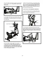
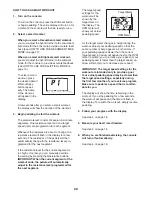
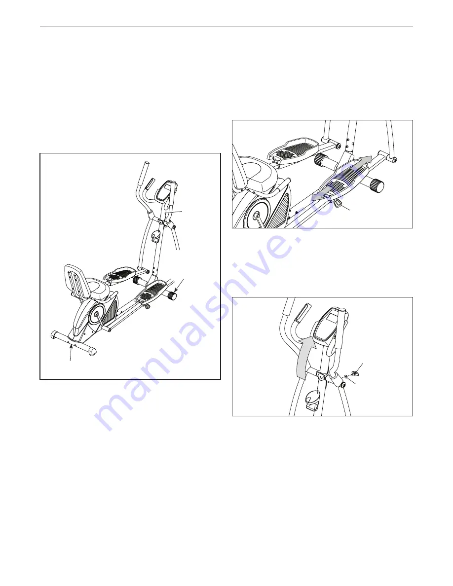
HOW TO ADJUST THE PEDAL POSITION
Each pedal can be adjusted to several positions. To
adjust the position of each pedal, loosen the pedal
knob, move the pedal forward or backward to the
desired position, and then retighten the pedal knob.
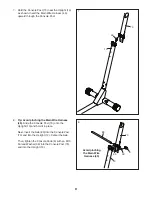
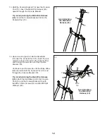
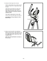
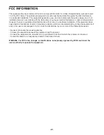
HOW TO USE THE ELLIPTICAL MODE
To use the hybrid trainer as an elliptical, first pivot the
upright to the high position and then tighten the con-
sole knob and the washer into the upright.
Upright
Lift here
Knob
Place
your foot
here
Knob
Washer


