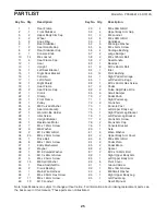
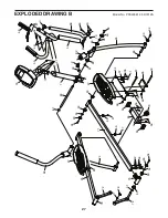
background image

25

PART LIST


Rear Frame


Front Stabilizer


Upper Body Arm Cap


Wheel


Snap Ring 


Rear Stabilizer


Seat Handle Cap


Rear Stabilizer Cap


Console Knob


10 

14 

M8 Locknut


11 

Seat Frame Cap


12 

Seat


13 

Upright


14 

Left Seat Bracket


15 

Right Seat Bracket


16 

Console


17 

Left Shield


18 

Right Shield


19 

Seat Frame


20 

Seat Frame Cap


21 

Crank


22 

Clamp


23 

Front Frame


24 

Pulley


25 

M6 Curved Washer


26 

Seat Handle Grip


27 

Water Bottle Holder


28 

Idler Screw


29 

Upright Bumper


30 

Resistance Motor


31 

M4 x 12mm Screw


32 

M6 Washer


33 

M10 x 98mm Bolt


34 

23 

M8 x 20mm Screw


35 

Drive Belt


36 

M8 x 10mm Screw


37 

Eddy Mechanism


38 

Magnet


39 

M10 Curved Washer


40 

M10 x 65mm Screw


41 

M4 x 25mm Screw


42 

15 

M8 Split Washer


43 

Reed Switch/Wire


44 

Crank Bearing


45 

Main Wire Harness


46 

M6 x 20mm Hex Screw


47 

17 

M4 x 16mm Screw


48 

10 

M10 Locknut


49 

M6 x 30mm Bolt


50 

Upper Body Arm Grip


51 

M6 Locknut


52 

M6 x 38mm Bolt


53 

Handlebar


54 

M8 Large Washer


55 

M4 x 5mm Screw


56 

Carriage Bushing


57 

Large Bumper


58 

M8 x 125mm Bolt


59 

Seat Handle


60 

Backrest


61 

M10 x 60mm Bolt


62 

Idler


63 

14 

Pivot Bushing


64 

Right Pedal Carriage


65 

Left Pedal Carriage


66 

M10 x 50mm Hex Screw


67 

Pedal


68 

Pulse Grip/Pulse Wire


69 

Small Bumper


70 

Pedal Knob


71 

Right Pedal Leg


72 

Crank Arm


73 

Console Post


74 

Left Upper Body Leg


75 

Right Pedal Leg Bracket


76 

Left Pedal Leg Bracket


77 

Crank Arm Screw


78 

Crank Arm Cap


79 

Console Bracket


80 

Axle


81 

Wave Washer


82 

Upper Body Arm Cover


83 

M8 x 40mm Bolt


84 

Pedal Plate


85 

Pedal Brace


86 

Spacer


87 

M10 x 102mm Bolt


88 

Right Upper Body Arm


89 

Left Upper Body Arm


90 

Pivot Cover


91 

Ground Screw


92 

M4 x 10mm Screw


93 

M8 Small Washer


94 

Right Upper Body Leg


95 

Left Pedal Leg


–– 

User’’s Manual

 Key No.  Qty. 

Description

 Key No.  Qty. 

Description

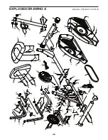
Model No. PFEL03812.0 R1012A

Note: Specifications are subject to change without notice.


For information about ordering replacement parts, see 

the back cover of this manual. *These parts are not illustrated.

Summary of Contents for HYBRID TRAINER

Page 1: ...UESTIONS If you have questions or if parts are damaged or missing DO NOT CONTACT THE STORE please contact Customer Care IMPORTANT Please register this product see the limited warranty on the back cove...

Page 2: ...OTING 22 EXERCISE GUIDELINES 24 PART LIST 25 EXPLODED DRAWING 26 ORDERING REPLACEMENT PARTS Back Cover LIMITED WARRANTY Back Cover This drawing shows the location s of the warning decal s If a decal i...

Page 3: ...pet from damage place a mat under the hybrid trainer 7 Inspect and properly tighten all parts regu larly Replace any worn parts immediately 8 Keep children under age 12 and pets away from the hybrid t...

Page 4: ...lease see the front cover of this manual To help us assist you note the product model number and serial number before contacting us The model number and the location of the serial number decal are sho...

Page 5: ...4 M6 x 30mm Bolt 49 4 Wave Washer 81 2 PART IDENTIFICATION CHART Use the drawings below to identify the small parts needed for assembly The number in parentheses below each drawing is the key number...

Page 6: ...u have a set of wrenches To avoid damaging parts do not use power tools ASSEMBLY 1 With the help of a second person place some of the packing materials not shown under the Rear Frame 1 Have the second...

Page 7: ...ire Tie 23 Hexagonal Holes 48 45 61 1 4 Tip Avoid pinching the Main Wire Harness 45 Slide the Front Frame 23 onto the Rear Frame 1 Attach the Front Frame with three M10 x 60mm Bolts 61 and three M10 L...

Page 8: ...re tie until the Main Wire Harness is routed through the Upright 6 Tip Avoid pinching the Main Wire Harness 45 Slide the Upright 13 onto the Front Frame 23 Attach the Upright with three M10 x 60mm Bol...

Page 9: ...ain Wire Harness 45 Slide the Console Post 73 onto the Upright 13 and hold it in place Next insert the Axle 80 into the Console Post 73 and into the Upright 13 Center the Axle Then tighten the Console...

Page 10: ...er 54 into each end of the Axle 80 at the same time 10 Identify the Right Pedal Carriage 64 which is attached to one of the Pedals 67 In addition identify the Right Pedal Leg 71 Loosen the Pedal Knob...

Page 11: ...de of the hybrid trainer See step 6 Tighten the three M10 x 60mm Bolts 61 11 Apply a generous amount of grease to the axle on the Right Upper Body Leg 94 Next slide a Spacer 86 and the Right Pedal Leg...

Page 12: ...d wire tie into the hole in the Console Post and then pull the wire tie out of the Console Bracket 79 Continue to pull the wire tie until the Pulse Wires 68 are routed into the Console Post 73 and thr...

Page 13: ...k of the Console 16 and insert batteries into the battery compartment Make sure to orient the bat teries as shown by the diagram inside the battery compartment Then reattach the bat tery cover 16 Have...

Page 14: ...Locknuts are inside the hexagonal holes Then slide the Upper Body Arm Cover 82 downward onto the Right Upper Body Leg 94 Assemble the Left Upper Body Arm 89 in the same way 19 Attach a Seat Handle 59...

Page 15: ...Extra parts may be included To protect the floor or carpet from damage place a mat under the hybrid trainer 20 20 Attach the Seat Frame 19 to the Rear Frame 1 with three M8 x 20mm Screws 34 and three...

Page 16: ...arefully move the hybrid trainer to the desired location and then lower it to the floor HOW TO ADJUST THE PEDAL POSITION Each pedal can be adjusted to several positions To adjust the position of each...

Page 17: ...te direction To dismount the hybrid trainer wait until the pedals come to a complete stop Note The hybrid trainer does not have a free wheel the pedals will con tinue to move until the flywheel stops...

Page 18: ...Reset button or begin pedaling The entire display will turn on for a moment the console will then be ready for use 2 Select the manual mode When you turn on the console the manual mode will be selecte...

Page 19: ...eset button To pause the console stop pedaling When the console is paused the time will flash in the display To continue your workout simply resume pedaling 5 Measure your heart rate if desired Note I...

Page 20: ...is too high or too low you can manually override the setting by pressing the Resistance buttons IMPORTANT When the current segment of the workout ends the pedals will automatically adjust to the resi...

Page 21: ...ence will not occur in a particular installation If this equipment does cause harmful interference to radio or television reception which can be determined by turning the equipment off and on the user...

Page 22: ...does not display correct feedback the reed switch should be adjusted To adjust the reed switch see EXPLODED DRAWING A on page 26 Remove the M4 x 16mm Screws 47 and the M4 x 25mm Screws 41 from the Lef...

Page 23: ...47 and the M4 x 25mm Screws 41 from the Left and Right Shields 17 18 Make sure to note which size of Screw you remove from each hole Then gently move the Left Shield out of the way Note For clarity t...

Page 24: ...c Exercise If your goal is to strengthen your cardiovascular system you must perform aerobic exercise which is activity that requires large amounts of oxygen for prolonged periods of time For aerobic...

Page 25: ...51 4 M6 Locknut 52 8 M6 x 38mm Bolt 53 1 Handlebar 54 6 M8 Large Washer 55 8 M4 x 5mm Screw 56 4 Carriage Bushing 57 2 Large Bumper 58 2 M8 x 125mm Bolt 59 2 Seat Handle 60 1 Backrest 61 6 M10 x 60mm...

Page 26: ...13 27 15 20 20 24 21 28 30 32 32 32 32 25 51 22 29 46 34 34 34 38 38 35 37 40 43 91 52 52 45 42 42 44 44 47 47 47 47 49 93 93 58 59 26 62 61 61 48 41 41 48 61 17 18 40 2 41 41 41 59 69 60 63 63 66 92...

Page 27: ...0 47 56 56 55 55 63 63 63 47 47 71 69 69 63 68 64 70 73 80 81 67 81 88 85 82 83 83 10 90 54 34 10 39 9 87 94 84 90 86 34 90 34 42 63 63 81 72 72 76 95 67 74 65 89 78 77 75 54 34 90 54 34 57 31 EXPLODE...

Page 28: ...d to freight damage to the product This warranty will automatically be voided if the product is used as a store display model if the product is purchased or transported outside the USA if all instruct...

Reviews: