background image

7

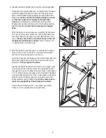
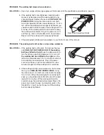
2. Identify the Right Upright (24) and the Left Upright (99).  

Straighten the Upright Wire (42), and feed it into the lower

end of the Right Upright (24) and out of the upper end.

Next, hold the Right Upright against the right side of the

Base (69); make sure that the Right Upright is turned

so that the upper end is angled in the direction

shown. Hand tighten two 3” Bolts (37) with one Star

Washer (63) and two Washers (45) into the Base and the

Right Upright; be careful not to damage the Upright

Wire.

With the help of a second person, carefully tip the tread-

mill onto its other side. Attach the Left Upright (99) and

the other Wheel (not shown) as described above and in

step 1. Make sure that the two small holes in the Left

Upright are positioned as shown. Note: There is not

an upright wire on the left side.

42

69

2

24

99

Small

Holes

37

45

63

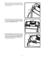
3.  With the help of a second person, carefully tip the tread-

mill so that it is flat on the floor, and raise the Uprights

(99, 24) to the vertical position as shown.

Hold the Crossbar (25) between the Left Upright (99) and

the Right Upright (24). Attach the Crossbar with two 3”

Bolts (37). Firmly tighten the Bolts.

Identify the Right Handrail (72), which has a large round

hole in the location shown. Route the Upright Wire (42)

through the hole in the Right Handrail. Next, hand tighten

a 2 1/4” Bolt (35) into the upper end of the Right Handrail

and the Right Upright (24). Then, hand tighten a Handrail

Bolt (27) with a Washer (45) into the lower end of the

Right Handrail and the Right Upright. Be careful not to

pinch the Upright Wire. Firmly tighten the Bolts.

Attach the Left Handrail (71) in the same way. Note:

There is not an upright wire on the left side.

35

25

37

37

27

45

45

27

35

71

42

72

24

99

Large

Hole

3

Summary of Contents for LX 450

Page 1: ...struc tions in this manual before using this equipment Save this manual for future reference QUESTIONS As a manufacturer we are com mitted to providing complete customer satisfaction If you have quest...

Page 2: ...STMENT 10 HOW TO FOLD AND MOVE THE TREADMILL 13 TROUBLESHOOTING 15 CONDITIONING GUIDELINES 17 ORDERING REPLACEMENT PARTS Back Cover LIMITED WARRANTY Back Cover Note An EXPLODED DRAWING and a PART LIST...

Page 3: ...l free telephone number on the front cover of this manual and order part number 146148 or see your local electronics store 12 Failure to use a properly functioning surge suppressor could result in dam...

Page 4: ...fter use before cleaning the treadmill and before performing the maintenance and adjustment procedures de scribed in this manual Never remove the motor hood unless instructed to do so by an authorized...

Page 5: ...To help us assist you note the product model number and serial number before calling The model number of the treadmill is PFTL31404 1 The serial number can be found on a decal attached to the tread mi...

Page 6: ...and your own phillips screwdriver adjustable wrench wire cutters and needlenose pliers For help identifying the assembly hardware refer to the PART IDENTIFICATION CHART below 1 Make sure that the powe...

Page 7: ...ot an upright wire on the left side 42 69 2 24 99 Small Holes 37 45 63 3 With the help of a second person carefully tip the tread mill so that it is flat on the floor and raise the Uprights 99 24 to t...

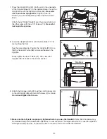
Page 8: ...place turn the connector and then insert it 6 72 47 47 5 Set the Console Base 47 on the Right Handrail 72 and the Left Handrail 71 Attach the Console Base with four 3 4 Screws 2 Start all four Screws...

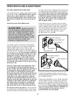
Page 9: ...are touching the floor See the lower drawing Position the Uprights 99 24 so that the treadmill Frame 86 is centered between the Uprights Firmly tighten the four 3 Bolts 37 Then raise the Uprights 99 2...

Page 10: ...malfunc tion or break down grounding provides a path of least resistance for electric current to reduce the risk of elec tric shock This product is equipped with a cord having an equipment grounding c...

Page 11: ...start the walking belt A moment after the button is pressed the walking belt will begin to move Hold the handrails and begin walking As you exercise change the speed of the walking belt as desired by...

Page 12: ...of measurement is selected remove the key and then reinsert it To reset the displays press the Stop button re move the key and then reinsert the key Measure your heart rate if desired To measure your...

Page 13: ...l until the storage latch closes over the catch Make sure that the storage latch is fully engaged over the catch To protect the floor or carpet from damage place a mat under the treadmill Keep the tre...

Page 14: ...to the left Pivot the treadmill down until the frame and foot rail are past the storage latch 2 Hold the treadmill firmly with both hands and lower the tread mill to the floor Do not drop the treadmil...

Page 15: ...turns off during use SOLUTION a Check the reset off circuit breaker located on the treadmill frame near the power cord see the drawing above If the circuit breaker has tripped wait for five minutes a...

Page 16: ...enter or slips when walked on SOLUTION a If the walking belt is off center first remove the key and UNPLUG THE POWER CORD If the walking belt has shifted to the left use the allen wrench to turn the l...

Page 17: ...r cardiovascular sys tem your exercise must be aerobic Aerobic exercise is activity that requires large amounts of oxygen for prolonged periods of time This increases the demand on the heart to pump b...

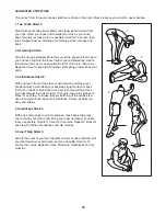
Page 18: ...les Stretch With one leg in front of the other reach forward and place your hands against a wall Keep your back leg straight and your back foot flat on the floor Bend your front leg lean forward and m...

Page 19: ...19 NOTES...
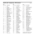
Page 20: ...Silver Screw 49 1 Filter Wire 50 1 Key Clip 51 1 Incline Motor 52 1 Incline Bracket 53 1 Incline Motor Bolt lower 54 3 Incline Pivot Bolt 55 2 Incline Pivot Nut 56 1 Motor Controller Wire 57 4 Round B...

Page 21: ...96 86 15 95 92 38 92 38 93 81 77 83 82 77 79 80 69 13 53 57 39 39 57 51 54 13 62 64 32 66 26 90 58 89 87 68 100 65 42 88 70 15 94 41 91 11 58 22 22 56 71 3 4 5 6 7 8 9 103 20 85 84 84 85 58 30 75 39 6...

Page 22: ...omer will be responsible for a minimal trip charge This warranty does not extend to any product or damage to a product caused by or attributable to freight damage abuse misuse im proper or abnormal us...

Reviews: