background image

Grease

7

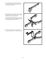
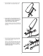
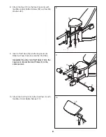
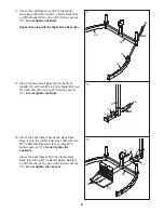
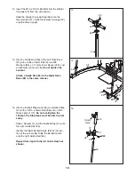
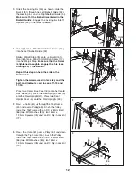
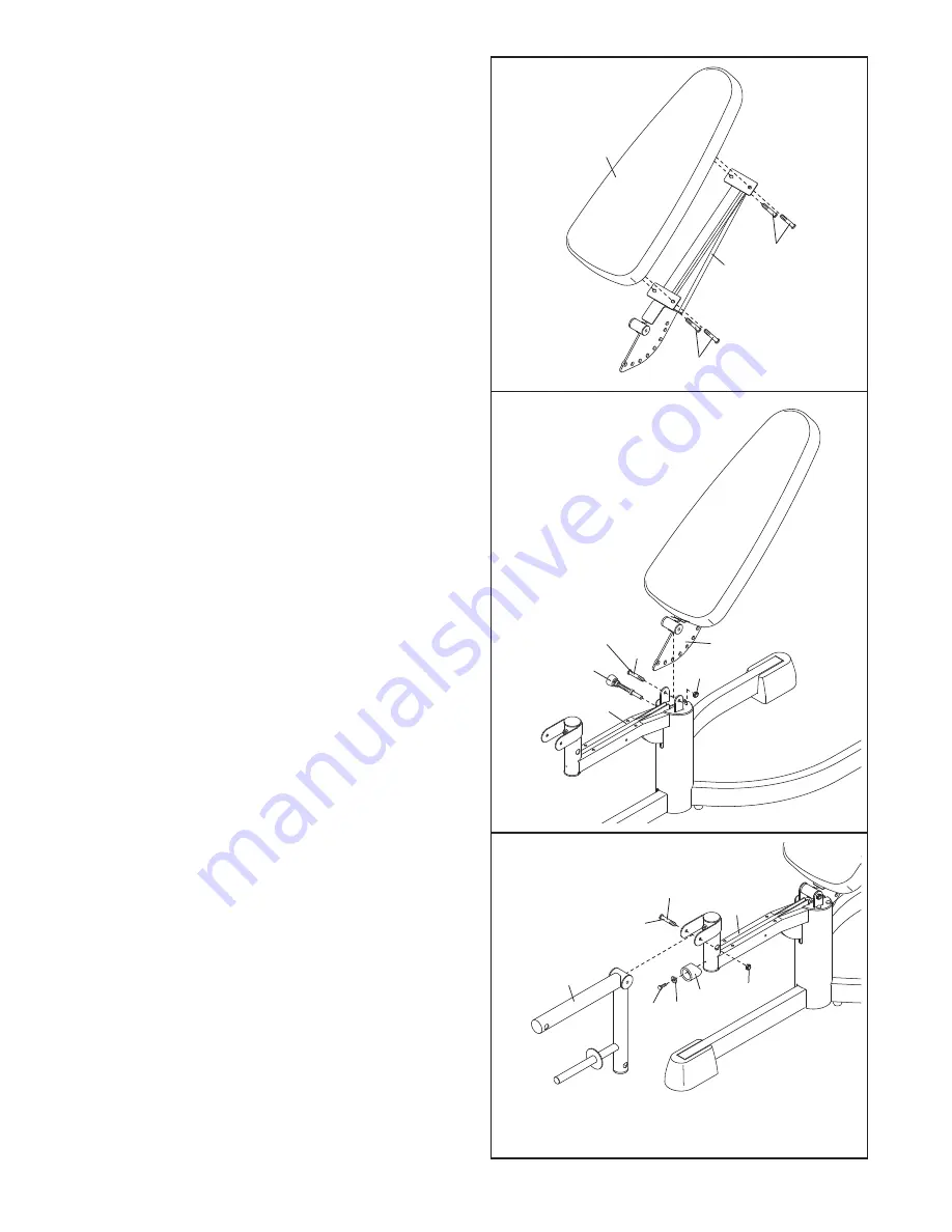
5.

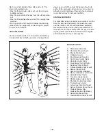
Attach the Backrest (11) to the Backrest Frame
(8) with four M6 x 15mm Button Screws (17).

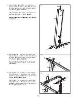
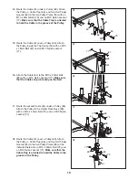
7.

Attach the Seat Bumper (27) to the Seat Frame
(5) with an M4 x 16mm Self-tapping Screw (91)
and an M4 Washer (84).

Grease an M10 x 82mm Button Bolt (93). Attach
the Leg Lever (6) to the Seat Frame (5) with the
Bolt and an M10 Nylon Locknut (77). 

Do not

overtighten the Locknut; the Leg Lever must
be able to pivot easily.

6.

Grease the M10 x 87mm Button Bolt (94). Attach
the Backrest Frame (8) to the Seat Frame (5)
with the Bolt and an M10 Nylon Locknut (77). 

Do

not overtighten the Locknut; the Backrest
Frame must be able to pivot easily.

Engage the Backrest Frame (8) with the Backrest
Knob (22) and fully tighten the Knob into the Seat
Frame (5).

8

11

17

5

6

17

5

8

94

77

22

5

7

93

77

27

84

91

6

Grease

Summary of Contents for PFANBE3525.0

Page 1: ...e the serial number in the space above for reference Serial Number Decal under seat QUESTIONS As a manufacturer we are committed to providing com plete customer satisfaction If you have questions or i...

Page 2: ...EXPLODED DRAWING are attached in the center of this manual Remove the PART IDENTIFICATION CHART and PART LIST EXPLODED DRAWING before begin ning assembly TABLE OF CONTENTS The decal shown here has be...

Page 3: ...rted into the backrest frame before exercising 11 Make sure that the cables remain on the pul leys at all times If the cables bind as you are exercising stop immediately and make sure that the cables...

Page 4: ...ght bench If you have questions after reading this manual call the telephone number on the warranty card accompanying this manual To help us assist you please note the product model number and serial...

Page 5: ...rts in a cleared area and remove the packing materials Do not dispose of the packing materials until assembly is completed As you assemble the weight bench make sure all parts are oriented as shown in...

Page 6: ...Base 1 with the indicated two M10 x 100mm Screws 26 3 Insert two M10 x 100mm Screws 26 up through the Base Plate 34 and the Seat Base 1 and the Right and Left Seat Bases 2 3 Attach the Right and Left...

Page 7: ...with the Bolt and an M10 Nylon Locknut 77 Do not overtighten the Locknut the Leg Lever must be able to pivot easily 6 Grease the M10 x 87mm Button Bolt 94 Attach the Backrest Frame 8 to the Seat Frame...

Page 8: ...ach the Curl Pad 13 to the Curl Post 7 with two M6 x 15mm Button Screws 17 9 Insert a Pad Tube 10 into the Leg Lever 6 Slide two Foam Pads 14 onto the Pad Tube Assemble the other two Pad Tubes 10 to t...

Page 9: ...Base 39 with two M10 x 63mm Button Bolts 90 and two M10 Nylon Locknuts 77 Do not tighten the Locknuts Attach the Foot Plate 49 to the Center Rack Base 39 with an M10 x 63mm Button Bolt 90 an M10 Washe...

Page 10: ...t easily Slide a Bumper 4 and the Barbell Stop 47 onto the right Guide Rod 46 Identify the Right Barbell Guide 53 by the loca tion of the screw hole Slide the Barbell Guide onto the right Guide Rod 46...

Page 11: ...t 43 with two M10 x 82mm Bolts 85 two M10 Washers 80 and an M10 Nylon Locknut 77 Do not tighten the Bolts Repeat this step with the left Front Upright not shown 19 Attach the Top Frame 45 to the Rear...

Page 12: ...d tighten an M6 x 15mm Button Screw 17 into the Weight Stop Make sure that the Screw is tightened enough to engage the hole see drawing 20 in the Barbell Repeat this step on the other side of the Barb...

Page 13: ...x 20mm Bolt 89 with an M10 Nylon Locknut 77 Make sure that the Cable can pivot easily on the Bolt 27 Route the second Cable 61 under a Pulley 63 Attach the Pulley to the Center Rack Base 39 with an M...

Page 14: ...the correct form for each exercise Make sure all parts are properly tightened each time the weight bench is used Replace any worn parts immediate ly The weight bench can be cleaned with a damp cloth...

Page 15: ...ht with the Spring Clips 72 Add weight to the Barbell 51 or Leg Lever not shown in the same manner Weights can be stored on the Center Rack Base 39 when they are not being used WARNING Always place an...

Page 16: ...y 63 closer to the upper Pulley Remove the M10 x 50mm Bolt 79 from the Pulley 63 the two Pulley Plates 35 the two Half Finger Guards 65 the Cable Trap 66 and the M10 Nylon Locknut 77 Reattach the Pull...

Page 17: ...that the cables and the cable traps have been assembled cor rectly If the cables have not been correctly routed the weight bench will not function properly and dam age may occur The numbers show the c...

Page 18: ...ll reshape and strengthen your body plus devel op your heart and lungs PERSONALIZING YOUR EXERCISE PROGRAM Determining the exact length of time for each workout as well as the number of repetitions or...

Page 19: ...ut List the date the exercises performed the resistance used and the numbers of sets and repetitions completed Record your weight and key body measurements at the end of every month Remember the key t...

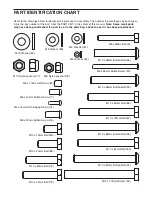
Page 20: ...45mm Bolt 75 M10 x 82mm Bolt 85 M10 x 78mm Bolt 87 M10 x 67mm Bolt 86 M10 x 20mm Bolt 89 M10 x 25mm Bolt 88 M10 x 63mm Button Bolt 90 M10 x 58mm Button Bolt 95 M10 x 100mm Screw 26 PART IDENTIFICATION...

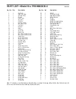
Page 21: ...de 53 1 Right Barbell Guide 54 2 Barbell Adapter 55 1 Lat Bar 56 4 Handgrip 57 2 Weight Carriage Bushing 58 1 Weight Carriage Stop 59 1 Rear Upright Foot 60 2 Center Base Foot 61 2 Cable 62 2 M8 x 10m...

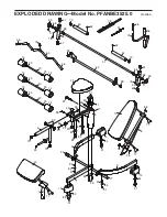
Page 22: ...10 14 25 25 14 6 19 19 29 30 3 2 8 11 28 28 36 17 17 7 13 17 94 91 93 77 77 81 92 92 81 84 91 84 91 84 91 77 84 91 26 34 84 84 91 84 91 95 55 56 56 71 52 68 68 69 67 67 16 33 50 51 53 54 68 68 69 67...

Page 23: ...6 76 76 74 80 77 87 77 80 80 86 87 77 86 80 86 80 80 48 47 67 67 77 88 4 46 46 47 48 67 67 88 77 4 42 57 57 58 61 70 70 77 89 63 63 65 65 65 65 66 66 79 77 35 35 39 60 60 63 75 77 77 80 86 80 86 80 70...

Page 24: ...us assist you be prepared to provide the following information the MODEL NUMBER of the product PFANBE3525 0 the NAME of the product PROFORM XP 300 weight bench the SERIAL NUMBER of the product see th...

Reviews: