background image

ASSEMBLY

Assembly requires two people.

Set the treadmill in a cleared area and remove all packing materials. Do not

dispose of the packing materials until assembly is completed.

Assembly requires your own phillips screw-

driver                       and rubber mallet                    .

Note: The underside of the treadmill walking belt is coated with high-performance lubricant. During shipping, a
small amount of lubricant may be transferred to the top of the walking belt or the shipping carton. This is a normal
condition and does not affect treadmill performance. If there is lubricant on top of the walking belt, simply wipe off
the lubricant with a soft cloth and a mild, non-abrasive cleaner.

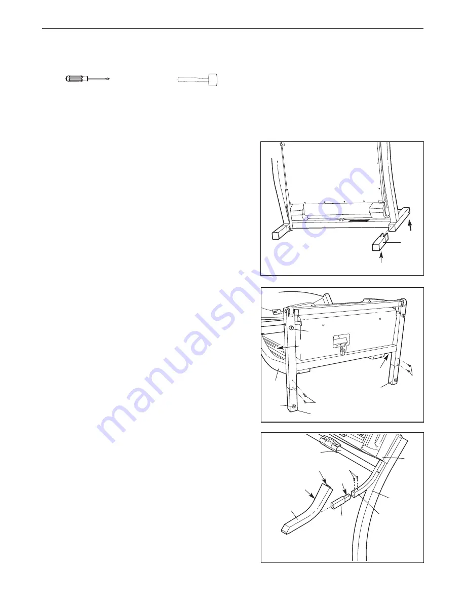
2. With the help of a second person, carefully lower the

treadmill frame and then tip the Uprights (69) down as
shown. 

Make sure that the Extension Legs (102) remain

in the Uprights. 

Attach each Extension Leg (102) with two of the six 3/4”
Screws (100) as shown. 

With the help of a second person, carefully tip the
Uprights (69) back to the vertical position.

Note: One replacement Base Pad (99) may be included.
Use the extra Base Pad if one becomes worn or needs to
be replaced.

100

102

69

99

99

Frame

69

100

102

1. With the help of a second person, carefully raise the

treadmill to the upright position as shown. 

While a second person tips the treadmill to one side
and holds it, insert one of the Extension Legs (102) into
the treadmill as shown. Make sure that the Extension
Leg is turned so the Base Pad (99) is on the bottom. 

Next, tip the treadmill to the other side and insert the
other Extension Leg (not shown) in the same way. Lower
the side of the treadmill so that both Extension Legs
(102) are resting flat on the floor.

102

99

1

3. Insert a Handrail Extension (66) into the post on the right

Upright (69) as shown; make sure that the indicated holes
are on top. Tap the Handrail Extension with a rubber mallet
to fully insert it. Attach the Handrail Extension with two 1/2”
Screws (67) as shown.

Identify the Right Foam Grip (75), which has a 

large 

cutout

in the left side for the Pulse Bar (76). Slide the Right Foam
Grip as far as possible onto the post on the right Upright
(69). (Note: It may be helpful to apply soapy water to the
Handrail Extension [66].) Make sure that the tab on the
Foam Grip is inserted into the Console Base (81). 

75

76

Cutout

Tab

66

Post

67

Holes

69

81

3

2

6

Summary of Contents for PFTL79102

Page 1: ...nce Visit our website at www proform com new products prizes fitness tips and much more QUESTIONS If you have questions or if there are missing parts we will guar antee complete satisfaction through d...

Page 2: ...T 8 HOW TO FOLD AND MOVE THE TREADMILL 19 TROUBLESHOOTING 20 CONDITIONING GUIDELINES 22 PART LIST 23 ORDERING REPLACEMENT PARTS Back Cover LIMITED WARRANTY Back Cover Note An EXPLODED DRAWING is attac...

Page 3: ...ly functioning surge suppressor could result in damage to the con trol system of the treadmill If the control sys tem is damaged the walking belt may change speed or stop unexpectedly which may result...

Page 4: ...plug the power cord immediately after use before cleaning the treadmill and before performing the main tenance and adjustment procedures de scribed in this manual Never remove the motor hood unless in...

Page 5: ...999 3756 Monday through Friday 6 a m until 6 p m Mountain Time excluding holidays To help us assist you please note the product model number and serial number before calling The model number of the tr...

Page 6: ...e the extra Base Pad if one becomes worn or needs to be replaced 100 102 69 99 99 Frame 69 100 102 1 With the help of a second person carefully raise the treadmill to the upright position as shown Whi...

Page 7: ...ft Upright 69 Make sure that the two Lock Pin Collars 72 and the Spring 71 are on the Lock Pin 74 Insert the Lock Pin into the Lock Knob Sleeve 70 and the left Upright 69 Tighten the Lock Knob 68 onto...

Page 8: ...vides a path of least resistance for electric current to reduce the risk of elec tric shock This product is equipped with a cord having an equipment grounding conductor and a grounding plug Plug the p...

Page 9: ...ition you can connect the treadmill to your VCR and TV and play iFIT com video programs videocas settes are available separately Video programs offer the same benefits as iFIT com CD programs but add...

Page 10: ...press the Start button or the Speed s s button Note During the first few minutes that the treadmill is used inspect the alignment of the walking belt and align it if necessary see page 21 Change the i...

Page 11: ...displayed heart rate appears to be too high or too low or if your heart rate is not displayed lift your thumbs off the sensor and allow the display to reset Then place your thumbs on the sensor as de...

Page 12: ...dicators in the columns will appear in the program display When the speed settings move to the left again and not all of the indicators in the Current Segment column are lit the speed settings will mo...

Page 13: ...layer Plug your headphones into the other side of the Y adapter HOW TO CONNECT YOUR PORTABLE STEREO Note If your stereo has an RCA type AUDIO OUT jack see instruction A below If your stereo has a 3 5m...

Page 14: ...INE OUT jack on your stereo HOW TO CONNECT YOUR COMPUTER Note If your computer has a 3 5mm LINE OUT jack see instruction A If your computer has only a PHONES jack see instruction B A Plug one end of t...

Page 15: ...key into the console See HOW TO TURN ON THE POWER on page 10 Select the iFIT com mode When the key is in serted the manual mode will be selected and the Manual indica tor will light To use iFIT com CD...

Page 16: ...page 15 Note If the speed or incline of the treadmill does not change when a chirp is heard Make sure that the iFIT com indicator is lit and that the Time Segment Time display is not flashing If the...

Page 17: ...ends the program will begin and the walking belt will begin to move Hold the handrails step onto the walking belt and begin walking During the program an electronic chirping sound will alert you when...

Page 18: ...gged in the key can be removed from the console and the displays and indicators on the console will automatically light in a preset sequence although the buttons on the console will not operate If a d...

Page 19: ...torage position in temperatures above 85 Fahrenheit HOW TO MOVE THE TREADMILL Before moving the treadmill convert the treadmill to the storage position as described above Make sure that the pin on the...

Page 20: ...e power turns off during use SOLUTION a Check the circuit breaker located on the treadmill frame near the power cord see c above If the circuit breaker has tripped wait for five minutes and then press...

Page 21: ...UNPLUG THE POWER CORD If the walking belt has shifted to the left use the allen wrench to turn the left rear roller bolt clockwise 1 2 of a turn if the walking belt has shifted to the right turn the b...

Page 22: ...goal is to strengthen your cardiovascular sys tem your exercise must be aerobic Aerobic exercise is activity that requires large amounts of oxygen for prolonged periods of time This increases the dem...

Page 23: ...Rear Isolator 64 2 Cushion Spacer 65 1 Left Foam Grip 66 2 Handrail Extension 67 8 1 2 Screw 68 1 Lock Knob 69 1 Upright 70 1 Lock Knob Sleeve 71 1 Spring 72 2 Lock Pin Collar 73 1 Pin Clip 74 1 Lock...

Page 24: ...39 80 80 83 45 46 50 2 51 1 53 52 114 49 49 49 56 57 58 34 59 60 59 34 61 49 53 54 110 53 62 109 48 111 112 53 113 44 96 80 83 101 31 118 118 54 55 64 120 34 64 120 34 49 63 63 28 28 122 56 29 EXPLODE...

Page 25: ...7 81 82 83 83 84 85 86 87 88 87 87 87 87 87 40 89 90 91 92 9 95 94 93 99 100 100 99 100 103 104 102 106 105 99 100 97 98 99 100 103 104 102 106 9 95 94 93 14 108 69 23 100 116 115 87 87 117 67 67 33 3...

Page 26: ...uct or damage to a product caused by or attributable to freight damage abuse mis use improper or abnormal usage or repairs not provided by an ICON authorized service center prod ucts used for commerci...

Reviews: