background image

7

ASSEMBLY

To hire an authorized service technician to assemble the treadmill, call toll-free 1-800-445-2480.

Assembly requires two persons.

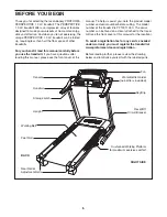
Set the treadmill in a cleared area and remove all packing materials. Do not

dispose of the packing materials until assembly is completed. Note: The underside of the treadmill walking belt is
coated with high-performance lubricant. During shipping, a small amount of lubricant may be transferred to the
top of the walking belt or the shipping carton. This is a normal condition and does not affect treadmill perfor-
mance. If there is lubricant on top of the walking belt, simply wipe off the lubricant with a soft cloth and a mild,
non-abrasive cleaner.

Assembly requires the included allen wrench      and your own phillips screwdriver                              and
wire cutters                .

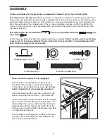
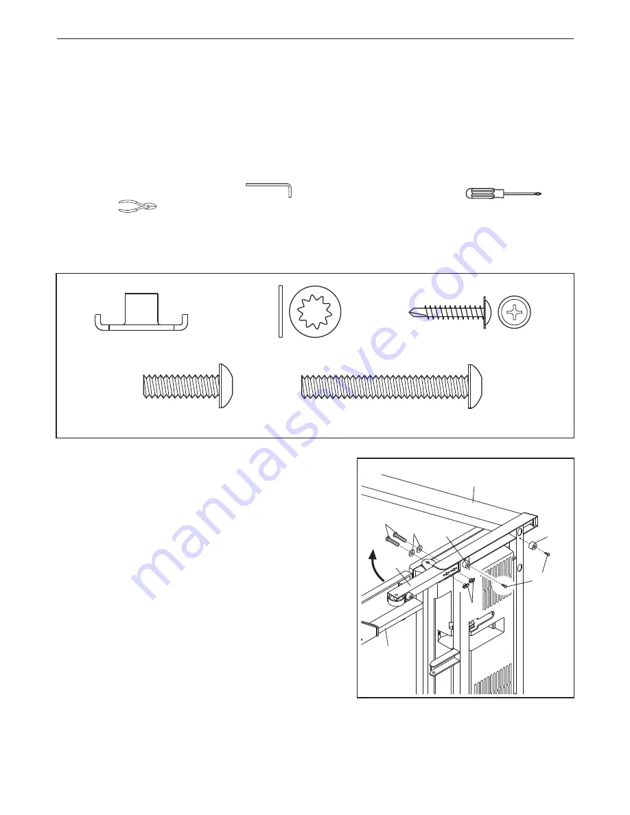
Use the drawings below to identify the hardware used during assembly. 

Note: If a part is not in the parts bag,

check to see if it has been preattached to one of the parts to be assembled. To avoid damaging plastic
parts, do not use power tools for assembly.
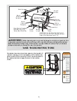
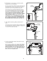
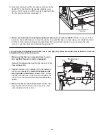
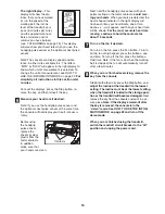
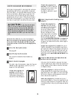
1.

Make sure that the power cord is unplugged.

With the help of a second person, carefully tip the
treadmill onto its left side as shown. Partially fold the
Frame (58) so the treadmill is more stable. 

Do not fully

fold the treadmill until it is completely assembled.

Attach four Base Pads (82) (only two are shown) to the
base of the Uprights (84) with four 1” Tek Screws (22). 

Insert an Extension Leg (89) into the base of the Uprights
(84) as shown. Hold two Extension Leg Nuts (67) in the
bottom of the Extension Leg. Next, insert two Extension
Leg Bolts (65) with Star Washers (8) into the top of the
Extension Leg, and firmly tighten the Extension Leg Bolts
into the Extension Leg Nuts. 

With the help of a second person, carefully tip the tread-
mill onto its other side. Attach the other Extension Leg
(not shown) as described above.

89

58

82

82

84

22

65

8

1

67

1” Tek Screw (22)–4

Star Washer (8)–8

Console Bolt (64)–4

Extension Leg Nut (67)–4

L

Extension Leg Bolt (65)–4

5

Summary of Contents for PFTL91105.0

Page 1: ... S MANUAL QUESTIONS As a manufacturer we are com mitted to providing complete customer satisfaction If you have questions or if parts are damaged or missing PLEASE CONTACT OUR CUSTOMER SERVICE DEPARTMENT DIRECTLY CALL TOLL FREE 1 888 533 1333 Mon Fri 6 a m 6 p m MST ON THE WEB www proformservice com Visit our website at www proform com new products prizes fitness tips and much more ...

Page 2: ...USTMENT 12 HOW TO FOLD AND MOVE THE TREADMILL 24 TROUBLESHOOTING 26 CONDITIONING GUIDELINES 29 PART LIST 31 ORDERING REPLACEMENT PARTS Back Cover LIMITED WARRANTY Back Cover Note An EXPLODED DRAWING is attached in the center of this manual 2 PROFORM is a registered trademark of ICON IP Inc ...

Page 3: ...r local PROFORM dealer or call the toll free telephone number on the front cover of this manual and order part number 146148 or see your local electronics store 12 Failure to use a properly functioning surge suppressor could result in damage to the con trol system of the treadmill If the control sys tem is damaged the walking belt may change speed accelerate or stop unexpectedly which may result i...

Page 4: ...ection to grounding electrodes and re quirements for the grounding electrode 27 An outside antenna system should not be lo cated in the vicinity of overhead power lines or other electric light or power circuits or where it can fall into such power lines or cir cuits When installing an outside antenna sys tem extreme care should be taken to keep from touching such power lines or circuits as contact...

Page 5: ... Read all instructions before using ICON assumes no responsibility for personal injury or property damage sustained by or through the use of this product SAVE THESE INSTRUCTIONS Power Lines Ground Clamps Ground Clamps Ground Clamp Bonding Jumper Standoff Insulators Antenna Lead in Wire Ground Wire Ground Wire Antenna Discharge Unit To External Antenna Terminal of Treadmill Mast Service Entrance Eq...

Page 6: ... assist you note the product model number and serial number before calling The model number of the treadmill is PFTL91105 0 The serial number can be found on a decal attached to the tread mill see the front cover of this manual for the location To avoid a registration fee for any service needed under warranty you must register the treadmill at www proformservice com registration Before reading fur...

Page 7: ...rts bag check to see if it has been preattached to one of the parts to be assembled To avoid damaging plastic parts do not use power tools for assembly 1 Make sure that the power cord is unplugged With the help of a second person carefully tip the treadmill onto its left side as shown Partially fold the Frame 58 so the treadmill is more stable Do not fully fold the treadmill until it is completely...

Page 8: ...e as sembly and locate the Console Wire Harness 78 Cut the plastic ties securing the Upright Wire Harness 77 to the right Upright 84 Next connect the Upright Wire Harness to the Console Wire Harness 78 Make sure to connect the connectors properly see the inset drawing The connectors should slide together easily and snap into place If the connectors do not slide together easily and snap into place ...

Page 9: ...cline increase and decrease buttons until the ball on the bracket is aligned with end of the Shock 92 Then press the end of the Shock onto the ball Note It may be necessary to press the end of the Shock onto the ball while the Frame is moving See drawing 7a Insert the Shock Pin 25 into the two in dicated small holes in the end of the Shock 92 Then rotate the Shock Pin until it clips onto the Shock...

Page 10: ...3 Make sure that no wires are pinched Reattach the Console 34 with the Screws 3 Discard the other wires included with the receiver A Wire 85 Small Cylinder 3 3 3 3 34 9 Make sure that all parts are properly tightened before you use the treadmill If there are sheets of clear plastic on the treadmill decals remove the plastic To protect the floor or carpet place a mat under the tread mill Note Extra...

Page 11: ...l frame near the power cord HOW TO CONNECT A 75 OHM CATV CABLE 1 Connect a 75 ohm CATV cable to the 75 ohm antenna terminal on the treadmill frame near the power cord HOW TO CONNECT A VCR 1 Connect one end of a 75 ohm CATV cable to the video output jack on your VCR 2 Plug in the power cord of your VCR See your VCR user s manual for proper grounding instructions 3 Connect the 75 ohm CATV cable to t...

Page 12: ...lfunc tion or break down grounding provides a path of least resistance for electric current to reduce the risk of elec tric shock This product is equipped with a cord having an equipment grounding conductor and a grounding plug Plug the power cord into a surge suppressor and plug the surge suppressor into an appropriate outlet that is properly installed and grounded in accordance with all local co...

Page 13: ... heart rate programs are also offered Each pro gram automatically adjusts the speed and incline of the treadmill to keep your heart rate near target heart rate settings while you exercise Note The heart rate pro grams require the use of the optional chest pulse sen sor Whether you select the manual mode or a program you can enjoy the shows of your choice on the per sonal television while you get i...

Page 14: ...lt as desired by pressing the Speed in crease and decrease buttons Each time a button is pressed the speed setting will change by 0 1 mph if a button is held down the speed setting will change in increments of 0 5 mph Note After the buttons are pressed it may take a moment for the walking belt to reach the selected speed setting If one of the numbered Speed buttons is pressed the walking belt will...

Page 15: ...t hold the handgrip pulse sensor with your palms resting on the metal contacts avoid mov ing your hands When your pulse is detected the heart shaped indicator in the right display will flash each time your heart beats one or two dashes will appear and then your heart rate will be shown For the most accurate heart rate reading continue to hold the contacts for about 15 seconds Turn on the fan if de...

Page 16: ...e first segment ends all speed settings in the matrix will move one column to the left The speed setting for the second segment will then be shown in the flashing Current Segment column and the treadmill will automatically adjust to the speed and incline set tings for the second segment Note If all of the in dicators in the Current Segment column are lit after the speed settings have moved to the ...

Page 17: ...s make sure that the in cline of the treadmill is at the lowest setting Next remove the key from the console and put it in a secure place Note If the displays and various indicators remain lit after the key is removed the console is in the demo mode See HOW TO USE THE INFORMATION MODE on page 22 and turn off the demo mode When you are finished using the treadmill switch the reset off circuit break...

Page 18: ...imum target heart rate setting of the pro gram will begin to flash If desired change the maxi mum target heart rate setting by pressing the increase or decrease button below the matrix see EXERCISE INTENSITY on page 29 Note If the maximum target heart rate setting is changed the intensity level of the entire program will change If heart rate program 10 is selected the word RATE will appear in the ...

Page 19: ... rate closer to the target heart rate set ting If the speed or incline setting is too high or too low at any time during the program you can adjust the setting with the Speed or Incline buttons However when the console compares your heart rate to the target heart rate setting the speed of the treadmill may automatically change to bring your heart rate closer to the target heart rate setting If you...

Page 20: ...set tings are not shown in the matrix To program a speed setting and an incline setting for the first segment simply adjust the speed and incline of the treadmill as desired by pressing the Speed and Incline buttons Every few times a Speed but ton is pressed an additional indicator will appear or disappear in the Current Segment column When the first segment of the program ends the current speed s...

Page 21: ...ll flash a se ries of tones will sound the speed setting and the incline setting will flash in the right display and all speed settings will move one column to the left The speed setting for the second segment will then be shown in the flashing Current Segment column and the treadmill will automatically adjust to the second speed and incline settings that you pro grammed previously The program wil...

Page 22: ...DE The console features an information mode that allows you to view treadmill usage information select a sys tem of measurement for the console and turn on and turn off the demo mode The information mode also al lows you to adjust the settings of the television and to save channels into the television s memory Follow the steps below to use the information mode Hold down the Stop button while inser...

Page 23: ...e connected an antenna to the treadmill the Air setting should be selected If you have connected a CATV cable one of the three Cable settings should be selected try all three Cable settings if necessary to find the best setting Press the On Off button again and save channels into the television s memory When the On Off button is pressed the television will begin scanning all of the channels availa...

Page 24: ...Raise the frame until the catch is past the latch pin Then slowly release the latch knob Make sure that the catch is securely held by the latch pin To protect the floor or carpet from damage place a mat under the treadmill Keep the treadmill out of direct sun light Do not leave the treadmill in the storage position in temperatures above 85 Fahrenheit HOW TO MOVE THE TREADMILL Before moving the tre...

Page 25: ...me down until the catch is past the latch pin 2 Hold the metal frame firmly with both hands and lower it to the floor CAUTION To decrease the possibility of in jury do not lower the frame by gripping only the plastic foot rails Do not drop the frame to the floor Make sure to bend your legs and keep your back straight Open Catch Latch Knob Frame Latch Pin ...

Page 26: ...e SOLUTION a Check the reset off circuit breaker see the drawing above If the circuit breaker has tripped wait for five minutes and then press the switch back in b Make sure that the power cord is plugged in If the power cord is plugged in unplug it wait for five minutes and then plug it back in c Remove the key from the console Reinsert the key into the console d If the treadmill still will not r...

Page 27: ...n the power cord insert the key and run the treadmill for a few minutes Repeat until the walking belt is properly tightened c If the walking belt still slows when walked on see the front cover of this manual PROBLEM The walking belt is off center or slips when walked on SOLUTION a If the walking belt is off center first remove the key and UNPLUG THE POWER CORD If the walking belt has shifted to th...

Page 28: ... appliances Try changing the position of the treadmill or other electric appliances to correct the problem Ghosts Ghosts are caused by the television signal following two paths one is the direct path and the other is reflected from tall buildings hills or other objects Change the direction or posi tion of the antenna to improve reception Blue Screen If the treadmill is located in the fringe area o...

Page 29: ...ty that requires large amounts of oxygen for prolonged periods of time This increases the demand on the heart to pump blood to the muscles and on the lungs to oxygenate the blood For aerobic exercise adjust the speed and incline of the treadmill until your heart rate is near the highest number in your training zone WORKOUT GUIDELINES Each workout should include the following three parts A Warm up ...

Page 30: ...illes Stretch With one leg in front of the other reach forward and place your hands against a wall Keep your back leg straight and your back foot flat on the floor Bend your front leg lean forward and move your hips toward the wall Hold for 15 counts then relax Repeat 3 times for each leg To cause further stretching of the achilles tendons bend your back leg as well Stretches Calves achilles tendo...

Page 31: ...alking Belt 49 1 Walking Platform 50 1 Motor Cover 51 1 Rear Roller 52 1 Left Rear Endcap 53 2 Rear Roller Bolt 54 1 Right Rear Endcap 55 1 Allen Wrench 56 1 Incline Stop Bracket 57 1 Ground Wire 58 1 Frame 59 1 Belly Pan 60 1 Reed Switch Bracket 61 1 Reed Switch Clip 62 1 Front Roller Nut 63 1 Reed Switch 64 4 Console Bolt 65 4 Extension Leg Bolt 66 4 Star Washer 67 4 Extension Leg Nut 68 2 Cauti...

Page 32: ... 53 40 52 54 33 57 53 12 15 43 28 55 70 70 32 32 62 45 11 66 69 4 3 27 26 5 5 5 83 42 83 93 94 1 1 93 94 5 5 90 90 91 6 3 6 3 24 40 17 91 33 36 101 95 102 98 97 99 96 100 29 50 33 33 38 39 33 66 103 103 103 103 103 2 2 7 7 83 3 30 5 5 104 105 EXPLODED DRAWING Model No PFTL91105 0 R0506A ...

Page 33: ...2 87 86 88 56 37 35 35 18 18 65 8 8 65 31 32 3 44 3 44 31 32 3 3 14 13 3 3 3 3 3 3 3 34 8 8 64 64 8 64 8 21 64 20 3 3 3 85 78 92 33 23 25 33 77 81 32 80 81 32 80 67 67 82 2 82 2 89 89 19 82 22 82 22 87 104 EXPLODED DRAWING Model No PFTL91105 0 R0506A ...

Page 34: ... the customer will be responsible for a minimal trip charge This warranty does not extend to any product or damage to a product caused by or attributable to freight damage abuse misuse im proper or abnormal usage or repairs not provided by an ICON authorized service center products used for commercial or rental purposes or products used as store display models No other warranty beyond that specifi...

Reviews: