background image

14

Turn on the fan if desired.

See step 6 on page 12.

When you are finished exercising, the console

will automatically turn off.

See step 7 on page 12.

HOW TO USE A PRESET PROGRAM

Preset programs 3, 4, 5, and 6 automatically change

the resistance of the pedals and prompt you to

increase or decrease your pedaling pace as they

guide you through effective workouts. The profiles

printed on the left side of the display show how the

resistance level and the target pace will change dur-

ing the preset programs.

Follow the steps below to use a preset program.

Turn on the console.

See step 1 on page 11.

Select a preset program.

To select preset

program 3, 4, 5, or

6, press the

Program button

repeatedly until

the number 3, 4,

5, or 6 appears

along the left side

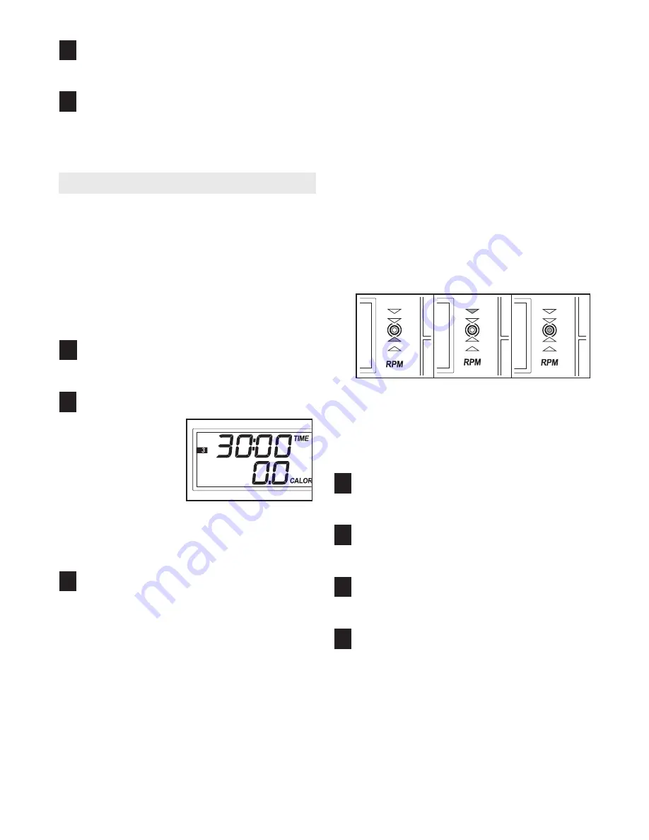
of the display. When a preset program is select-

ed, the display will show how long the program

will last. 

Begin pedaling to start the program.

Each preset program consists of several time

periods of different lengths. One resistance level

and one target pace are programmed for each

period.  

At the end of each period of the program, the

resistance level will flash in the display for a few

seconds. The resistance of the pedals will then

automatically change to the resistance level that

is programmed for the next period. Note: If the

resistance level is too high or too low, you can

override it by pressing the Increase and

Decrease buttons. However, when the current

period ends, the resistance level will automatical-

ly change if a different resistance level is pro-

grammed for the next period.

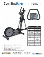
During the program, the pace guide will prompt

you to increase or decrease your pedaling pace.

When one of the two lower indicators lights,

increase your pace; when one of the two upper

indicators lights, decrease your pace. When the

center indicator lights, maintain your current

pace. Important: The pace guide is intended

only to provide a goal. Make sure to pedal at a

pace that is comfortable for you. 

The display will show the time remaining in the

program. If you stop pedaling for a few seconds,

the program will pause and the time will flash in

the display. To restart the program, simply resume

pedaling.

Monitor your progress with the display.

See step 4 on page 12. 

Measure your heart rate if desired.

See step 5 on page 12.

Turn on the fan if desired.

See step 6 on page 12.

When you are finished exercising, the console

will automatically turn off.

See step 7 on page 12.

7

6

5

4

3

2

1

8

7

Summary of Contents for StrideSelect 825

Page 1: ...reference Model No PFCCEL3906 2 Serial No _ Serial Number Decal QUESTIONS As a manufacturer we are com mitted to providing complete customer satisfaction If you have questions or if parts are damaged...

Page 2: ...SEMBLY 5 HOW TO USE THE ELLIPTICAL EXERCISER 10 MAINTENANCE AND TROUBLESHOOTING 15 CONDITIONING GUIDELINES 16 PART LIST 17 EXPLODED DRAWING 18 HOW TO ORDER REPLACEMENT PARTS Back Cover LIMITED WARRANT...

Page 3: ...pounds 8 Wear appropriate exercise clothes when using the elliptical exerciser Always wear athletic shoes for foot protection while exer cising 9 Hold the handgrip pulse sensor or the han dlebars whe...

Page 4: ...tions after reading this manual please see the front cover of this manual To help us assist you note the product model number and serial number before call ing The model number is PFCCEL3906 2 The ser...

Page 5: ...ntify small parts The number in parentheses below each drawing is the key number of the part from the PART LIST on page 17 The number following the parentheses is the quantity needed for assembly Note...

Page 6: ...ews into the Front Stabilizer 3 Next slide the Mast 15 onto the Button Screws and against the Front Stabilizer Make sure that the Mast is oriented as shown While another person holds the Mast 15 and t...

Page 7: ...tery door Reattach the battery door 5 5 Batteries Batteries Battery Cover Make sure the wire harnesses do not get pinched and damaged during this step 4 2 46 67 15 83 83 95 86 76 72 Hexagonal Holes 4...

Page 8: ...he same way 8 16 14 84 53 75 7 Slide the Right Crank Arm 38 onto the four indicated welded bolts make sure that the Right Crank Arm is in the indicated cutout in the Pedal Disk 8 Next finger tighten f...

Page 9: ...e Pivot Axle Slide a Handlebar Spacer 25 onto the short tube on the Left Handlebar 9 and rotate the Handlebar Spacer so the small arrow is pointing toward the floor Next slide the Left Handlebar onto...

Page 10: ...est pedal first Then step off the lowest pedal HOW TO USE THE HANDLEBARS The handlebars are designed to add upper body exer cise to your work outs Push and pull the handlebars as you exercise to work...

Page 11: ...gram see page 13 To use a preset program see page 14 Before using the console make sure that batteries are installed see assembly step 5 on page 7 If there is a sheet of clear plastic on the display r...

Page 12: ...r the most accurate heart rate reading continue to hold the handgrip pulse sensor for about 30 seconds Note If you continue to hold the hand grip pulse sensor the display will show your heart rate for...

Page 13: ...in the display instead of your heart rate Begin pedaling to start the program Pulse program 1 is 30 minutes long and is divided into several time periods of different lengths One target heart rate is...

Page 14: ...the display for a few seconds The resistance of the pedals will then automatically change to the resistance level that is programmed for the next period Note If the resistance level is too high or too...

Page 15: ...he result of low batteries See assembly step 5 on page 7 for replacement instructions HANDGRIP PULSE SENSOR TROUBLESHOOTING Avoid moving your hands while using the handgrip pulse sensor Excessive move...

Page 16: ...strengthen your cardiovascular sys tem your exercise must be aerobic Aerobic exer cise is activity that requires large amounts of oxygen for prolonged periods of time This increases the demand on the...

Page 17: ...45 2 Adjustment Knob 46 7 M8 Nylon Locknut 47 2 Crank Screw 48 2 Hub Cover 49 1 M6 x 8mm Screw 50 4 M8 x 45mm Button Bolt 51 1 Return Spring 52 1 Magnet Guide 53 6 M8 Washer 54 1 C Magnet 55 1 Motor 5...

Page 18: ...Model No PFCCEL3906 2 R0906A 46 2 6 9 10 11 22 23 91 67 53 71 71 24 15 74 22 23 24 53 91 27 28 27 86 79 46 50 24 25 26 24 89 81 87 72 76 27 28 28 79 27 5 50 46 24 25 26 24 89 7 66 66 74 66 66 66 74 74...

Page 19: ...5 18 18 38 88 45 19 17 20 93 65 92 42 42 80 8 21 40 47 57 80 92 14 18 18 88 45 42 42 20 19 17 36 93 65 47 57 40 21 48 82 66 53 66 66 53 53 66 16 84 84 43 1 78 69 66 77 66 29 55 61 62 90 90 62 49 3 32...

Page 20: ...ge or repairs not provided by an ICON authorized service center to prod ucts used for commercial or rental purposes or to products used as store display models No other war ranty beyond that specifica...

Reviews: