JOKER EVOLUTION 33
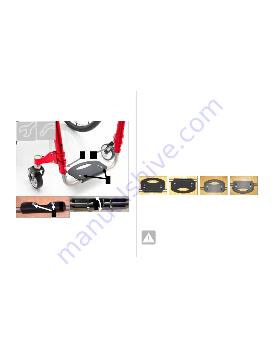
Standard footplate
The support tube for the footrest has several pre-drilled holes and the
frame has a further hole allowing the height of the footrest to be
adjusted
(figure 50).
Remove the bolts and nuts “A” (3mm aleen key and 8mm
spanner) that fix the aluminium plate that is now to be
removed.
Loosen the bolts and nuts “B” on the central support “S”
(4mm Allen key and 10mm spanner).
These first two steps are necessary to make the distance
between the two footplates tubes wider or narrower so as to
keep the same tapering inclination of the fames. In fact the
width of the footplate changes with relation to its length : the
longer footplate distance, the narrower its width.
Remove the bolts, washers and nuts “C” and “C
1
” (4mm Allen
key and 8mm spanner.
Slide the footplate tubes up or down to the desired height.
Insert the bolts "C" into the nearest holes and tighten them
Lean the aluminium plate on the central support “S” to check
or adjust its inclination.
To change inclination, turn the central support “S” as shown
by the arrow in picture 50.
Remove the aluminium plate.
Tighten the bolts and nuts “B” hard.
Assemble the aluminium plate and fix it with the bolts and
nuts “A”.
Position of the footplate
The aluminium plate can be assembled in four different positions:
completely internal (figures 50, 51a), completely external (figure
51b), 2/3 internal (figure 51c), 2/3 external (figure 51d). These
configurations depends only on how the parts are assembled. The
position can be chosen on the order form.
After the adjustment, check the front wheel, when
rotating, does not touch the footplate.
(see also chapter 6.5 “Adjustment of front wheels height
and fork”).
8 3-4
C C
1
Fig. 50
A
S S
B
Fig. 51a Fig. 51b Fig. 51c Fig. 51d


