background image


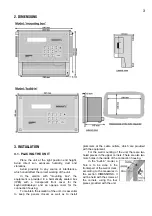
2. DIMENSIONS 


3. INSTALLATION 


3.1. PLACING THE UNIT 


Place the unit at the right position and height. 

Avoid direct sun exposure, humidity, dust and 
vibrations. 

Avoid proximity to any source of interference, 

which could affect the correct working of the unit. 

In the version with "mounting box", the 

equipment is provided in a hermetically sealed box 
(IP65) with a transparent front cover for the 
keyboard/displayer and an opaque cover for the 
connection housing. 

To maintain the isolation of the unit, it is essential 

to keep the panels closed, as well as to install 

grommets at the cable outlets, which are provided 
with the equipment. 

For the wall mounting of the unit, there are two 

holed pieces in the upper corners. There are also two 

more holes in the inside of the connection housing. 

In the “built-in” model, a 

hole  is  to  be  done  in  the 
frontal part of the wall or desk, 

according to the measures in 
the section DIMENSIONS. It 
will be held with the screws at 
the corners, using the four 
pieces provided with the unit. 


Summary of Contents for Agronic

Page 1: ...re are 3 different models according to the number of filters to control for 6 12 and 18 filters Models for 6 and 12 filters can be increased whenever necessary up to 18 sending them back to the factor...

Page 2: ...flow and volume total of filtered water For the detection of breakdowns in the installation For different options A timing for detection delay can be assigned to the inputs in order to avoid inadequa...

Page 3: ...er and an opaque cover for the connection housing To maintain the isolation of the unit it is essential to keep the panels closed as well as to install grommets at the cable outlets which are provided...

Page 4: ...that those cables supply other units or elements If the battery is far away from the controller use high section cables and make a reduction when entering the equipment The input is also protected wit...

Page 5: ...rk properly a There is a black stripe on the screen Unplug the unit open it remove the keyboard and with a screwdriver cross the two contacts on the central part of the left side marked as J3 during t...

Page 6: ...o the outputs see indicative stick Without the bridge the outputs are working to 12 Vdc and with the bridge installed they will have a voltage near to 24 volts From the company the units are delivered...

Page 7: ...nsion for the Fulfilment of the Product Security The fulfilment of the following specifications was demonstrated as indicated in the Official Diary of the European Communities Emissions EN 50081 1 94...

Page 8: ...will only be asked if the unit was configured to work by volume Impulse value is the value of the water which has circulated every time the volumetric counter gives an impulse The value can go from 00...

Page 9: ...re gauge The third screen asks whether these data are to be erased by time by volume 5 6 CONSULTATION On pressing the CON key the following screen will be displayed The first screen shows the number o...

Page 10: ...10 R 910 1...

Reviews: