background image

Glass Shade


Flat Area

Raised Dimples

Light Kit Fitter

ssembly

Screws

Light Kit

Pan

White

Blue

Black

      Molded

Adaptor Plugs

White

9.

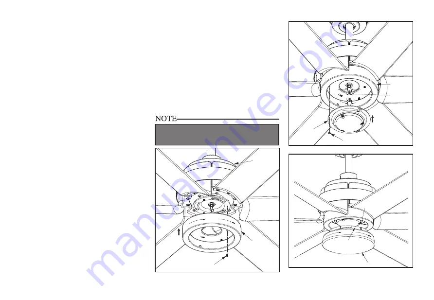
Installing the Light Kit 

Pan/Light Kit Fitter 

Assembly/ Glass Bowl

CAUTION - To reduce the risk of electrical 

shock, disconnect the electrical supply circuit 

to the fan before installing the light kit.
1.  Loosen but do not remove two of three 

mounting screws from the fan motor 

assembly; Remove one mounting screw. 

(Figure 17)

2.  Push the light kit pan up to the fan motor 

assembly so that the two loosened screw 

heads fit into the keyhole slots. Turn the 

light kit pan clockwise, tightened the 

screws. Re-install the screw that was 

removed in step 1 and tighten firmly. 

(Figure 17)

3.  Remove one screw from the light kit pan 

and loosen, but do not remove the other 

two screws. Connect the wires from the 

light kit fitter assembly to the wires from 

the fan motor assembly by connecting the 

molded adaptor plugs together. Carefully 

tuck all wires and splices into the switch 

cap. (Figure 17)

4.  Push the light kit fitter assembly up so 

that the two loosened screw heads fit into 

the keyhole slots. Turn the light kit fitter 

assembly clockwise, tighten the screws. Re-

install the screw that was removed in step 3 

and tighten firmly. (Figure 18)

5.  Place the glass bowl into the light kit pan, 

aligning the three flat areas on the top of 

the glass bowl with the three raised dimples 

in the light kit pan. Turn the glass bowl 

clockwise until it stops. (Figure 19)

Screws

Light Kit

 Pan

Motor

Assembly

Figure 17

Figure 18

PERIODICALLY CHECK THE GlASS BOWL  IS 

SEATED FULLY CLOCKWISE IN THE LIGHT KIT 

PAN ASSEMBLY.

Figure 19

Summary of Contents for AirPro P250003

Page 1: ... P250003 ...

Page 2: ...first 30 days for replacement After 30 days the original purchaser MUST contact Progress Lighting at 864 678 1000 for repair or replacement which shall be determined in Progress Lighting s sole discretion and shall be purchaser s sole and exclusive remedy Labor and Shipping Excluded This warranty does not cover any costs or fees associated with the labor including but not limited to electrician s ...

Page 3: ...ty Rules Unpacking Your Fan Installing Your Fan Setting the Codes Making the Electrical Connections Operating Your Fan Care of Your Fan Troubleshooting Specifications Table of Contents 1 2 3 6 7 10 11 11 12 ...

Page 4: ...ors should be turned upward and pushed carefully up into electrical box The wires should be spread apart with the grounded conductor and the equipment grounding conductor on one side of the electrical box and ungrounded conductor on the other side of the electrical box 11 Electrical diagrams are for reference only Light kits that are not packed with the fan must be UL Listed and marked suitable fo...

Page 5: ...11 Transmitter and Receiver 12 Extension Lead Wire 1 Mounting Bracket inside canopy 2 6 Ball Downrod Assembly hanger pin and locking pin pre attached 3 Canopy with Canopy Ring attached 4 Decorative Motor Collar Cover 5 Fan Motor Assembly 6 Blades 6 2 Unpacking Your Fan Unpack your fan and check the contents You should have the following items a b 1 2 3 4 5 6 7 8 9 10 11 12 2h 4h 8h R 3 4 2 5 1 6 O...

Page 6: ...ical box Note You may need a longer downrod to maintain proper blade clearance when installing on a steep sloped ceiling The maximum angle allowable is 20 If the canopy touches downrod remove the decorative canopy bottom cover and turn the canopy 180 before attaching the canopy to the mounting plate To hang your fan where there is an existing fixture but no ceiling joist you may need an installati...

Page 7: ...ten the blades to the flywheel by installing the screws to the side of flywheel 4 Make sure all the screws are firmly tightened Figure 6 Figure 5 Figure 6 Figure 7 Motor Assembly Screws Decorative Ring Attaching the Decorative Ring 1 Remove the three screws from the tab of fan motor assembly Attach the decorative ring to the fan motor assembly by aligning the holes on decorative ring with the hole...

Page 8: ... not remove the set screws on the collar on the top of the motor housing 6 Align the holes at the bottom of the downrod with the holes in the collar on top of the motor housing Figure 10 7 Carefully insert the hanger pin through the holes in the collar and downrod Be careful not to jam the hanger pin against the wiring inside the downrod Insert the locking pin through the hole near the end of the ...

Page 9: ...ng bracket is properly seated in the groove in the hanger ball Figure 12 WHEN USING THE STANDARD BALL DOWNROD MOUNTING THE TAB IN THE RING AT THE BOTTOM OF THE MOUNTING BRACKET MUST REST IN THE GROOVE OF THE HANGER BALL FAILURE TO PROPERLY SEAT THE TAB IN THE GROOVE COULD CAUSE DAMAGE TO WIRING UL Listed Electrical Box Ceiling Mounting Bracket Hook 120V Wires Washers Mounting Screws Supplied with ...

Page 10: ...ovided by connecting the molded adaptors together Figure 15 BLUE BLUE BLACK WHITE WHITE Remote Receiver WHITE L N BLACK GREY BROWN BLUE BROWN GREY GREEN WHITE WHITE BLUE BLUE SUPPLY CIRCUIT Installing the Receiver into the Mounting Bracket 1 Position the house supply wires to one side of the slide on mounting bracket position the fan wires to the opposite sid 2 Insert the narrow end of the receive...

Page 11: ...s 3 Make sure that canopy is tightened securely to ceiling mounting bracket and that the ceiling mounting bracket is tightened securely to the electrical box 4 Interchanging two adjacent blades can redistribute the weight and possibly result in the smoother operation 5 Use the enclosed Blade Balancing Kit if the blade wobble is still noticeable Touching Ceiling 8 Finishing the Fan Installation STA...

Page 12: ... one screw from the light kit pan and loosen but do not remove the other two screws Connect the wires from the light kit fitter assembly to the wires from the fan motor assembly by connecting the molded adaptor plugs together Carefully tuck all wires and splices into the switch cap Figure 17 4 Push the light kit fitter assembly up so that the two loosened screw heads fit into the keyhole slots Tur...

Page 13: ...witch or breaker box 5 Return power to the fan at the wall switch or breaker box 6 Press and release the Learn button located in the remote s battery compartment within 30 seconds of turning on the power 7 If pairing is successful the fan s light kit will flash and the blades will begin to spin 8 Replace the battery cover on the remote control NOTE The remote control has already been paired to the...

Page 14: ...ed to 5 Press and release 6 turns the fan speed to 6 Fan OFF Turns fan Off Light ON OFF Press and release the light button to turn the light on Press and release the light button to turn the light off Dimmer Press and hold up dimmer button to decrease the light level Press and hold the down dimmer button to increase the light level Timer Light on Decreases the light level Dimmer Forward Reverse Co...

Page 15: ...CTION MAKING ELECTRICAL CONNECTIONS Fan will not start Fan sounds noisy 1 Check main and branch circuit fuses or breakers 2 Check line wire connections to the fan and switch wire connections in the switch housing CAUTION Make sure main power is off 3 Check batteries in the transmitter Does the red LED light come on Are you standing close enough to the fan Normal range is 10 20 feet Are the dip swi...

Page 16: ...arantee that interference will not occur in a particular installation If this equipment does cause harmful interference to radio or television reception which can be determined by turning the equipment off and on the user is encouraged to try to correct the interference by one or more of the following measures Reorient or relocate the receiving antenna Increase the separation between the equipment...

Reviews: