5.
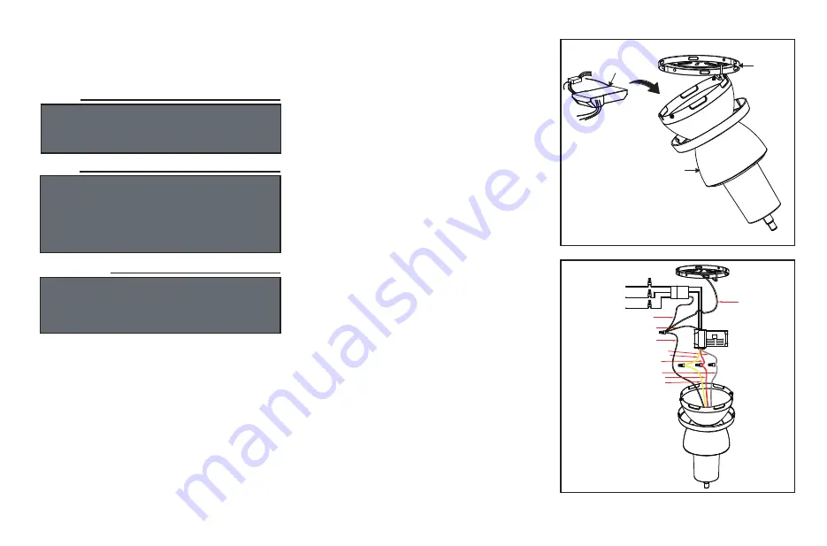
Figure 6
Figure 7
Ceiling
bracket
assembly
Motor assembly
Receiver
Making the Electrical
Connections
If you feel you do not have enough electrical
wiring knowledge or experience, have your fan
installed by a licensed electrician.
1.
2.
3.
(Figure 6) Insert the receiver into the
Ceiling bracket assembly
with the flat side
of the receiver facing the ceiling.
(Figure 7) Motor to receiver electrical
connections: Connect the grey wire from the
fan to the
grey wire from the receiver. Connect
the red wire from the fan to the red wire
from the receiver. Connect the yellow
wire from
the fan to the yellow wire from the receiver.
Secure the wire connections with the plastic
wire connecting nuts provided.
(Figure 7) Receiver to house supply wires
electrical connections: Connect the black (hot)
wire from the ceiling to the black wire marked
"AC in L" from the receiver. Connect the white
(neutral) wire from the ceiling to the white wire
marked "AC in N" from the receiver. Secure
the wire connections with
the plastic wire
connecting nuts provided.
4. (Figure 7) If your outlet box has a ground
wire (green or bare copper) connect it to the fan
ground wires; otherwise connect the ceiling
bracket assembly ground wire to the mounting
bracket. Secure the wire connection with a
plastic nut provided. After connecting the wires
spread them apart so that the green and white
wires are on one side of the outlet box and grey/red
and yellow
wires are on the other side. Carefully
tuck the wire connections up into the outlet box.
TO AVOID POSSIBLE ELECTRICAL SHOCK, BE
SURE ELECTRICITY IS TURNED OFF AT THE
MAIN FUSE BOX BEFORE WIRING.
NOTE
NOTE
FAN MUST BE INSTALLED AT A MAXIMUM
DISTANCE OF 20 FEET FROM THE
TRANSMITTING UNIT FOR PROPER
SIGNAL TRANSMISSION BETWEEN THE
TRANSMITTING UNIT AND THE FAN'S
RECEIVING UNIT.
WARNING
CHECK TO SEE THAT ALL CONNECTIONS ARE
TIGHT, INCLUDING GROUND, AND THAT NO
BARE WIRE IS VISIBLE AT THE WIRE NUTS.
EXCEPT FOR THE GROUND WIRE.
Yellow
Gray
Red
Ground wire
Ground wire
Gray
Yellow
Red
Ground wire
AC IN L(Black)
AC IN N(White)
Ground wire
Ground wire
Summary of Contents for AirPro Willacy P250063
Page 1: ...Ceiling Fan Installation Manual P250063 93133628_A ...
Page 14: ...11 Wifi Control Setup Smart Device Control ...
Page 15: ...Wifi Control Setup Smart Speaker Voice Control 12 ...
Page 18: ...Manuel d installation du ventilateur de plafond P250063 93133628_A ...
Page 31: ......
Page 32: ......
Page 35: ...Manual de Instalación del Ventilador de Techo P250063 93133628_A ...
Page 48: ...11 Configuration du contrôle WIFI Contrôle des appareils intelligents ...
Page 49: ...Configuration du contrôle WIFI Contrôle vocal intelligent du haut parleur 12 ...


