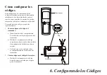
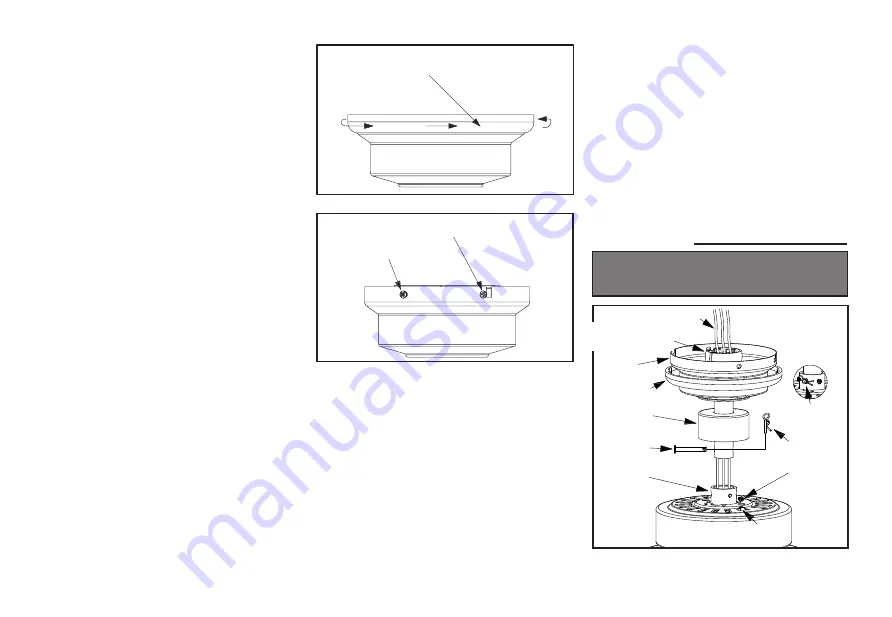
Girar la cubierta para quitar
4.
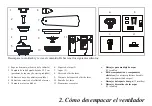
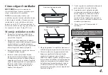
Cómo colgar el ventilador
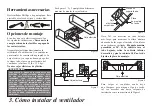
RECUERDA
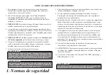
cortar el suministro de
electricidad. Sigue los pasos más abajo para
colgar correctamente tu ventilador.
NOTA: Se recomienda instalar este
ventilador en techo interior estándar usando
el tubo bajante incluido. Cuando uses una
instalación de techo estándar con el tubo
bajante de 6 plg (15.2 cm) suministrado, la
distancia desde el techo a la parte inferior de
las aspas será de unas 10 plg (25.4 cm).
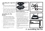
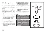
Montaje estándar en techo
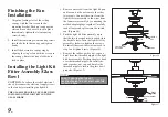
1. Retira el aro de la cubierta, girándolo en
sentido contrario a las agujas del reloj hasta
que se libere. (Figura 5)
2. Retira el soporte de montaje de la cubierta
aflojando los cuatro tornillos en la parte superior
de ella. Quita los dos tornillos sin ranura y
afloja los tornillos ranurados. Esto te permitirá
retirar el soporte de montaje (Figura 6)
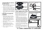
3.
Retira los pasadores de soporte y de cierre en
el conjunto del tubo bajante.
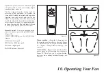
4. Inserta los cables que salen por la parte
superior del motor del ventilador, a través de
la cubierta decorativa del collarín del motor y
enseguida por el aro de la cubierta. Asegúrate
de que las ranuras queden en la parte superior.
Inserta los cables a través de la cubierta y
enseguida a través del conjunto del tubo
bajante y bola. (Figura 7)
Remove
Loosen but Do Not Remove
Figura 5
Figura 6
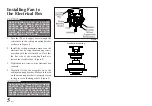
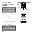
5.
Afloja, sin quitarlos, los tornillos de fijación en el
collarín de la parte superior de la carcasa de motor.
6. Alinea los orificios en la parte inferior del tubo
bajante con aquellos del collarín en la parte
superior de la carcasa de motor (Figura 7).
Inserta con cuidado el pasador de soporte a través
de los orificios del collarín y del tubo bajante. Ten
cuidado de no apretar contra el cableado dentro
del tubo bajante. Inserta el pasador de cierre en
el orificio cercano al extremo del perno hasta
que encaje en su posición, como se muestra en el
círculo de la Figura 7.
7.
Vuelve a apretar los tornillos del collarín en la
parte superior de la carcasa del motor.
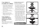
8.
Asegúrate de que el ojal quede instalado
correctamente en la cubierta del collarín y
desliza enseguida la cubierta del collarín
por el tubo bajante hasta quedar sobre la
carcasa del motor. Asegúrate de que tanto la
cubierta como la cubierta del collarín estén
orientadas correctamente.
9.
Pasa a la sección "Cómo instalar el
ventilador".
SI NO INSTALAS BIEN LOS TORNILLOS DE FIJACIÓN,
COMO SE INDICA EN EL PASO 7, PUEDEN AFLOJARSE Y
POSIBLEMENTE SE CAERÁ EL VENTILADOR.
Figura 7
Motor collar
Pin in locked
position
Locking pin
Tighten
screws
Reverse
switch
Hanger pin
Motor collar
cover
Canopy ring
Motor wires
Ball/Downrod
assembly
Canopy
Aflojar pero no quitar
Quitar
Cables del motor
Conjunto de tubo
bajante/bola
Interruptor
de reversa
Aprieta
los tornillos
Pasador
de cierre
Pasador
en posición
de cierre
Collarín
del motor
Pasador
de soporte
Cubierta
del collarín
del motor
Aro de la
cubierta
Cubierta
ADVERTENCIA


