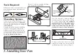
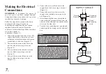
background image

4.

Hanging the Fan

REMEMBER

 to turn off the power. Follow 

the steps below to hang your fan properly.
NOTE: This fan is recommended for 

standard ceiling mount using the downrod 

provided with this fan. When using standard 

ceiling installation with the 6 inch downrod 

provided, the distance from the ceiling  

to the bottom of the fan blades will be 

approximately 10 inches.

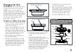
Standard Ceiling Mounting

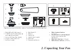
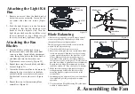
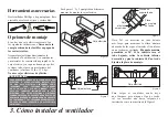
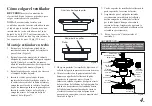
1.  Remove the canopy ring from the canopy 

by turning the ring counter-clockwise 

until it unlocks. (Figure 5)

2.  Remove the mounting bracket from the 

canopy by loosening the four screws on 

the top of the canopy. Remove the two 

non-slotted screws and loosen the slotted 

screws. This will enable you to remove 

the mounting bracket. (Figure 6)

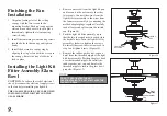
3.  Remove the hanger pin and locking pin 

from downrod assembly

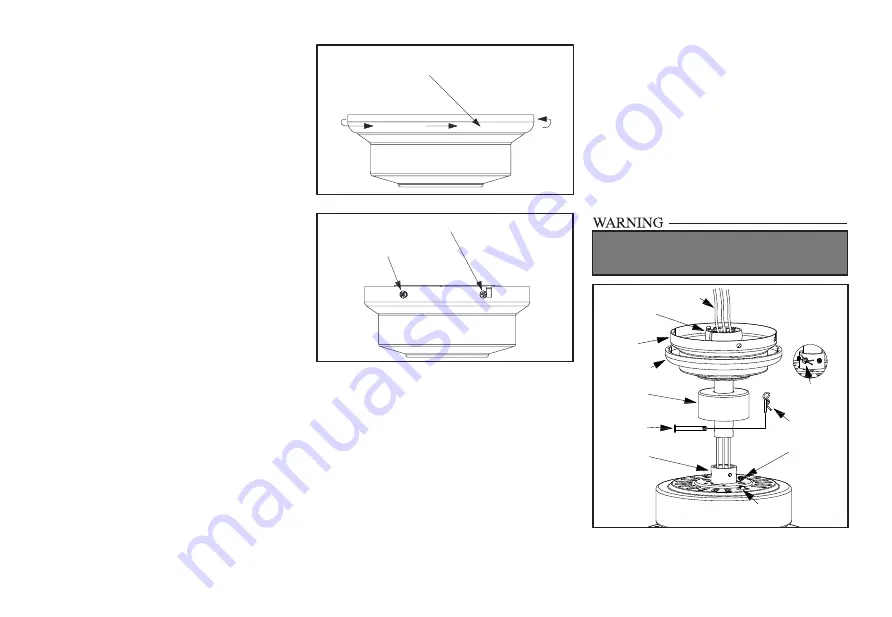
4.  Route the wires exiting the top of the fan 

motor through the decorative motor collar 

cover then the canopy ring. Make sure the 

slot openings are on top. Route the wires 

through the canopy and then through the 

ball/downrod assembly. (Figure 7)

Remove

Loosen but Do Not Remove

Turn Canopy to Remove

Figure 5

Figure 6

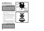
5.  Loosen, but do not remove, the set  screws 

on the collar on the top of the motor 

housing.

6.  Align the holes at the bottom of the 

downrod with the holes in the collar on top 

of the motor housing. (Figure 7) 

Carefully insert the hanger pin through the 

holes in the collar and downrod. Be careful 

not to jam the hanger pin against the wiring 

inside the downrod. Insert the locking pin 

through the hole near the end of the bolt 

until it snaps into its locked position, as 

noted in the circle inset of Figure 7.

7.  Re-tighten the set screws on the collar on 

top of  the motor housing.

8.  Make sure the grommet is properly installed 

in the collar cover, then slide the collar cover 

on the downrod until it rests on the motor 

housing. Be sure that the canopy and the 

collar cover are both oriented correctly.

9.   Proceed to “Installing the Fan” section.

FAILURE TO PROPERLY INSTALL SET SCREWS 

AS NOTED IN STEP 7 COULD RESULT IN FAN 

LOOSENING AND POSSIBLY FALLING.

Figure 7

Motor collar

Pin in locked

position

Locking pin

Tighten

screws

Reverse

switch

Hanger pin

Motor collar

cover

Canopy ring

Motor wires

Ball/Downrod

assembly

Canopy

Summary of Contents for P250020

Page 1: ... P250020 93103997_A ...

Page 2: ...first 30 days for replacement After 30 days the original purchaser MUST contact Progress Lighting at 864 678 1000 for repair or replacement which shall be determined in Progress Lighting s sole discretion and shall be purchaser s sole and exclusive remedy Labor and Shipping Excluded This warranty does not cover any costs or fees associated with the labor including but not limited to electrician s ...

Page 3: ...ty Rules Unpacking Your Fan Installing Your Fan Setting the Codes Making the Electrical Connections Operating Your Fan Care of Your Fan Troubleshooting Specifications Table of Contents 1 2 3 6 7 10 11 11 12 ...

Page 4: ...aking electrical connections spliced conductors should be turned upward and pushed carefully up into electrical box The wires should be spread apart with the grounded conductor and the equipment grounding conductor on one side of the electrical box and ungrounded conductor on the other side of the electrical box 11 Electrical diagrams are for reference only Light kits that are not packed with the ...

Page 5: ...5 7 Blades 5 8 Light Kit Pan 9 Light Kit Fitter Assembly 10 Glass Shade 11 Transmitter and Receiver 1 Mounting Bracket inside canopy 2 6 Ball Downrod Assembly hanger pin and locking pin pre attached 3 Canopy with Canopy Ring attached 4 Decorative Motor Collar Cover 5 Fan Motor Assembly 2 Unpacking Your Fan Unpack your fan and check the contents You should have the following items 1 2 3 4 5 6 7 8 9...

Page 6: ...trical box Note You may need a longer downrod to maintain proper blade clearance when installing on a steep sloped ceiling The maximum angle allowable is 20 If the canopy touches downrod remove the decorative canopy bottomcoverandturnthecanopy180 before attaching the canopy to the mounting plate To hang your fan where there is an existing fixture but no ceiling joist you may need an installation h...

Page 7: ...nrod assembly Figure 7 Remove Loosen but Do Not Remove Turn Canopy to Remove Figure 5 Figure 6 5 Loosen but do not remove the set screws on the collar on the top of the motor housing 6 Align the holes at the bottom of the downrod with the holes in the collar on top of the motor housing Figure 7 Carefully insert the hanger pin through the holes in the collar and downrod Be careful not to jam the ha...

Page 8: ... box by using the mounting screws provided with the electrical box Note that the flat side of the mounting bracket is toward the electrical box Figure 8 3 Tighten the two screws on the electrical box securely 4 Carefully lift the fan assembly up to the ceiling mounting bracket Make sure the tab on the mounting bracket is properly seated in the groove in the hanger ball Figure 9 Figure 8 WHEN USING...

Page 9: ...Setting the code on the transmitter a Remove the battery cover from the battery compartment on the back side of the transmitter b Slide code switches to your choice of up or down position factory setting is up c Replace the battery cover on the battery compartment of the transmitter 2 Setting the code on the receiver a Slide code switches to the same position as set on your transmitter 1 2 3 4 ON ...

Page 10: ...e the wire connecting nuts supplied with your fan and supplied with remote control Secure the connectors with electrical tape Make sure there are no loose strands or connections Figure 11 1 Connect the ground conductor of the 120v supply this may be a bare wire or a wire with green colored insulation to the green ground lead s of the fan Figure 11 2 Connect the fan motor white wire to the receiver...

Page 11: ...of the blades Measure from a point on the center of each blade to the point on the ceiling Measure this distance as shown in Figure 15 Rotate the fan until the next blade is positioned for measurement Repeat for each blade Measurements deviation should be within 1 8 Run the fan for 10 minutes 3 Make sure that canopy is tightened securely to ceiling mounting bracket and that the ceiling mounting br...

Page 12: ...1 and tighten firmly Figure 16 3 Remove the rubber gasket nut cap and finial from the threaded nipple of the light kit fitter assembly Position the glass bowl over the threaded nipple Re install the rubber gasket nut cap and finial to the threaded nipple to secure the glass bowl properly Figure 17 Screws Light Kit Pan Light Kit Fitter Assembly Blue Black White Glass Shade Rubber washer Finial Nut ...

Page 13: ... the opposite direction and reverse airflow Figure 19 Figure 20 Warm weather Forward A downward air flow creates a cooling effect as shown in Figure 19 This allows you to set your air conditioner on a higher setting without affecting your comfort Cool weather Reverse An upward air flow moves warm air off the ceiling are as shown in Figure 20 This allows you to set your heating unit on a lower sett...

Page 14: ...CTION MAKING ELECTRICAL CONNECTIONS Fan will not start Fan sounds noisy 1 Check main and branch circuit fuses or breakers 2 Check line wire connections to the fan and switch wire connections in the switch housing CAUTION Make sure main power is off 3 Check batteries in the transmitter Does the red LED light come on Are you standing close enough to the fan Normal range is 10 20 feet Are the dip swi...

Page 15: ...guarantee that interference will not occur in a particular installation If this equipment does cause harmful interference to radio or television reception which can be determined by turning the equipment off and on the user is encouraged to try to correct the interference by one or more of the following measures Reorient or relocate the receiving antenna Increase the separation between the equipme...

Page 16: ... Manual de instalación del ventilador de techo P250020 93103997_A ...

Page 17: ...30 días siguientes a la compra Pasados 30 días el comprador original TIENE que contactar a Progress Lighting llamando al 864 678 1000 para reparación o reposición según determine Progress Lighting a su entera discreción y este será el único y exclusivo remedio del comprador Se excluyen cargos por mano de obra y envío Esta garantía no cubre ningún costo ni cargo asociado a la mano de obra incluyend...

Page 18: ...car el ventilador Cómo instalar el ventilador Configurando los códigos Cómo hacer las conexiones eléctricas Cómo usar el ventilador Cuidado del ventilador Solución de problemas Especificaciones Tabla de contenido 1 2 3 6 7 10 11 11 12 ...

Page 19: ...os conductores empalmados deben voltearse hacia arriba y empujarse con cuidado dentro de la caja eléctrica Los cables deben estar separados con el cable y el conductor a tierra del equipo hacia uno de los lados de la caja eléctrica y el conductor sin conexión a tierra hacia el lado opuesto 11 Los diagramas eléctricos son sólo para referencia Los kits de luces no empaquetados con el ventilador tien...

Page 20: ...l kit de luces 9 Conjunto del soporte del kit de luces 10 Pantalla de vidrio 11 Transmisor y receptor 1 Soporte de montaje dentro de la cubierta 2 Conjunto de tubo bajante bola de 15 2 cm pasadores de soporte y de cierre prefijados 3 Cubierta con aro de cubierta acoplado 4 Cubierta decorativa del collarín del motor 5 Conjunto motor ventilador 2 Cómo desempacar el ventilador Desempaca tu ventilador...

Page 21: ...tilador en un techo muy inclinado El ángulo máximo permitido es 20º Si la cubierta toca el tubo bajante retira la cubierta inferior decorativa y gira la cubierta 180º antes de fijarla a la placa de montaje Para colgar el ventilador donde haya una lámpara pero ninguna viga de techo tal vez necesites una barra colgante de instalación como se muestra en la Figura 4 PARA REDUCIR EL RIESGO DE INCENDIO ...

Page 22: ...s de fijación en el collarín de la parte superior de la carcasa de motor 6 Alinea los orificios en la parte inferior del tubo bajante con aquellos del collarín en la parte superior de la carcasa de motor Figura 7 Inserta con cuidado el pasador de soporte a través de los orificios del collarín y del tubo bajante Ten cuidado de no apretar contra el cableado dentro del tubo bajante Inserta el pasador...

Page 23: ...cluidos Nota que el lado plano del soporte de montaje está hacia la caja eléctrica Figura 8 3 Aprieta bien los dos tornillos en la caja eléctrica 4 Con cuidado alza el conjunto del ventilador hasta el soporte de montaje en el techo Asegúrate de que la pestaña en el soporte de montaje esté bien asentada dentro de la ranura de la bola de soporte Figura 9 Figura 8 EN EL MONTAJE ESTÁNDAR DE TUBO BAJAN...

Page 24: ...o configurar el código del transmisor a Quita la cubierta del compartimento de las baterías en la parte posterior del transmisor b Desliza los interruptores de código como desees hacia arriba o hacia abajo la configuración de fábrica es hacia arriba c Coloca de nuevo la cubierta sobre el compartimento de las baterías del transmisor 2 Cómo configurar el código del receptor a Desliza los interruptor...

Page 25: ...es con cinta aislante Asegúrate de que no haya conexiones ni cables sueltos Figura 11 1 Conecta el conductor a tierra del cable de 120 V puede ser un cable desnudo o un cable con aislante verde al los cable s terminal es a tierra verde s del ventilador Figura 11 2 Conecta el cable blanco del motor del ventilador al cable blanco del receptor usando una tuerca de cable Figura 11 3 Conecta el cable n...

Page 26: ... en el centro de cada aspa al punto en techo Mide esta distancia como muestra la Figura 15 Gira el ventilador hasta que la siguiente aspa quede en posición para medir Repite el procedimiento para cada aspa Las desviaciones de la medición no deben pasar de 1 8 3 2 mm Enciende el ventilador por 10 minutos 3 Asegúrate de que la cubierta esté bien fijada al soporte de montaje en el techo y de que este...

Page 27: ...rmemente Figura 16 3 Retira la junta de goma la tuerca la tapa y el remate de la boquilla roscada del conjunto del soporte del kit de luces Coloca el tazón de vidrio sobre la boquilla enroscada Vuelve a instalar la junta de hule la tuerca la tapa y el remate en la boquilla roscada para asegurar bien el tazón de vidrio Figura 17 Tornillos Carcasa del kit de luces Conjunto del soporte del kit de luc...

Page 28: ...r el ventilador Las aspas del ventilador girarán en sentido contrario e invertirán la corriente de aire Clima cálido Hacia adelante Un flujo de aire hacia abajo surte efecto refrescante como se muestra en la Figura 19 Esto permite fijar tu aire acondicionado en configuración más alta sin afectar tu comodidad Clima frío Reversa Un flujo de aire hacia arriba desplaza el aire cálido lejos del techo c...

Page 29: ... principales y secundarios 2 Verifica las conexiones de cables en línea al ventilador y de cables del interruptor en la caja de interruptores PRECAUCIÓN Asegúrate de que la fuente principal de electricidad esté apagada 3 Verifica las baterías en el transmisor Se enciende la luz LED roja Estás lo suficientemente cerca del ventilador El rango normal es de 10 20 pies 3 a 6 metros Coinciden las config...

Page 30: ...unicaciones radiales Sin embargo no hay garantía de que no ocurrirá interferencia en una instalación particular Si este equipo causa interferencia perjudicial a la recepción de radio o televisión que puede determinarse encendiendo y apagando el equipo se recomienda al usuario tratar de corregir la interferencia con una o más de las siguientes medidas Reorientar o reubicar la antena receptora Incre...

Reviews: