20
CUTTING HEIGHT ADJUSTMENT
:
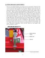
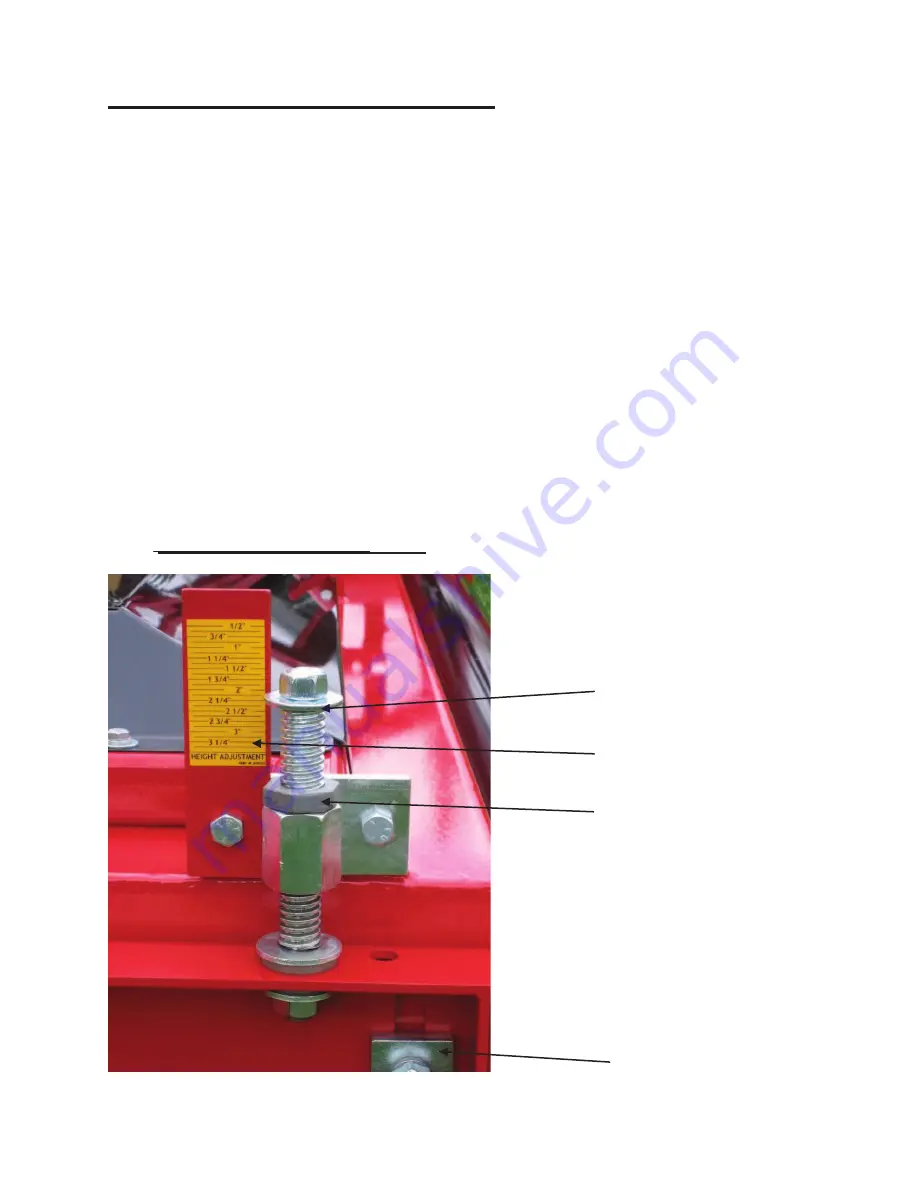
There are four height adjusters per mowing deck. Each adjuster (located in each
corner of the deck) must be adjusted to the same height to ensure a smooth even
cut. A wrench for this purpose is provided. In addition, each deck must be
adjusted the same so that a level cut is obtained across the whole cutting width of
the mower. Mower cutting height adjustment is made by turning a 5/8” nut on
top of an acme threaded rod which makes up the height adjuster. A washer under
the nut indicates the height against the decal. There are an infinite number of
adjustments available from ½” to 4”. Moving the adjuster up and down moves a
side channel that mounts the front and rear rollers. Before attempting to make
height adjustments, the locking bolt on the side channel adjacent to the adjuster
must be loosened. When the desired adjustment is made, be sure to tighten the
locking bolt and adjuster jam nut to maintain the adjusted height. The height
decals at the back of the deck are set 1/4” lower, so that the back actually cuts
1/4” higher, this will provide a better but, prolong the life of the blades, and
reduce horsepower requirement. This will also make the side channel look
uneven, but this is correct.
TDR-12 HEIGHT ADJUSTMENT
Side channel lock bolt
Height indicator
washer
Height scale
Jam nut
Summary of Contents for 1212029
Page 2: ...3 ...
Page 4: ...5 ...
Page 36: ...33 ...
Page 38: ...BLADE SPINDLE ASSEMBLY 2 1 2 3 4 6 7 8 9 10 11 12 14 15 17 13 16 5 ...
Page 40: ...2 3 4 5 6 8 9 10 11 15 16 17 16 15 18 19 1 22 23 REAR DECK ASSEMBLY 21 20 12 7 14 13 24 4 ...
Page 44: ...GEARBOX MOUNT ASSEMBLY 1 3 4 5 6 7 9 10 12 11 8 2 13 8 ...
Page 46: ...3 2 4 5 13 12 14 15 10 5 16 7 11 WING ASSEMBLY 10 1 11 17 9 3 6 8 7 ...
Page 52: ...HYDRAULICS ASSEMBLY 1 2 3 4 5 18 8 9 10 11 14 11 17 16 15 14 13 9 5 12 6 7 6 19 5 10 16 20 ...
Page 54: ......
Page 56: ...20 DECK GEARBOX REAR DECK AND RIGHT DECK ...
Page 58: ...22 LEFT DECK GEARBOX ...
Page 60: ...24 4 WAY GEARBOX ASSEMBLY ...
Page 63: ...REAR DECK PTO SHAFT 27 ...
Page 64: ...28 INPUT PTO SHAFT ...
Page 65: ...INPUT PTO SHAFT B MODELS TDR 15 SERIAL 1215102B AND UP TDR 12 SERIAL 1312031B AND UP 29 ...
Page 66: ......


