27
BLADE REMOVAL AND INSTALLATION
:
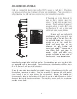
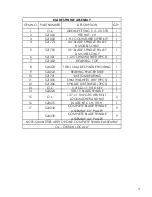
Two, 1/2” X 1 3/4” grade 5 bolts with lock washers and nuts hold blade to
blade spindle support bar. When changing blades, be sure that these fasteners are in
good condition so they will not come loose during operation.
BLADE SHARPENING
:
IMPORTANT
-
When sharpening blades be sure to balance them. Unbalanced
blades will cause excessive vibration, which can damage blade spindle bearings.
Vibration may also cause structural cracks in spindle housing.
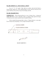
Follow original sharpening pattern as shown. Sharpen blade to a razor edge.
Protect hands when sharpening. Do not sharpen backside of blade.
BLADE SHARPENING
Summary of Contents for 1212029
Page 2: ...3 ...
Page 4: ...5 ...
Page 36: ...33 ...
Page 38: ...BLADE SPINDLE ASSEMBLY 2 1 2 3 4 6 7 8 9 10 11 12 14 15 17 13 16 5 ...
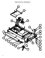
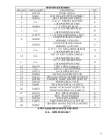
Page 40: ...2 3 4 5 6 8 9 10 11 15 16 17 16 15 18 19 1 22 23 REAR DECK ASSEMBLY 21 20 12 7 14 13 24 4 ...
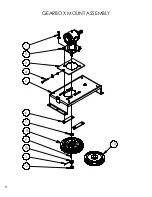
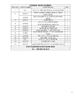
Page 44: ...GEARBOX MOUNT ASSEMBLY 1 3 4 5 6 7 9 10 12 11 8 2 13 8 ...
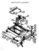
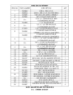
Page 46: ...3 2 4 5 13 12 14 15 10 5 16 7 11 WING ASSEMBLY 10 1 11 17 9 3 6 8 7 ...
Page 52: ...HYDRAULICS ASSEMBLY 1 2 3 4 5 18 8 9 10 11 14 11 17 16 15 14 13 9 5 12 6 7 6 19 5 10 16 20 ...
Page 54: ......
Page 56: ...20 DECK GEARBOX REAR DECK AND RIGHT DECK ...
Page 58: ...22 LEFT DECK GEARBOX ...
Page 60: ...24 4 WAY GEARBOX ASSEMBLY ...
Page 63: ...REAR DECK PTO SHAFT 27 ...
Page 64: ...28 INPUT PTO SHAFT ...
Page 65: ...INPUT PTO SHAFT B MODELS TDR 15 SERIAL 1215102B AND UP TDR 12 SERIAL 1312031B AND UP 29 ...
Page 66: ......

