background image

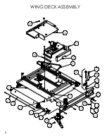
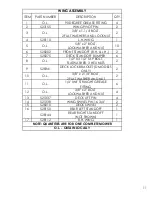
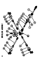
WING DECK ASSEMBLY

1

2

3

5

6

7

9

8

10

11

12

13

14

15

16

17

16

15

18

19

20

21

22

26

23

24

25

4

6

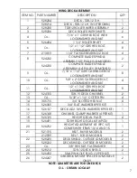
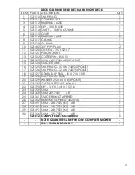
ITEM NO.

PART NUMBER

DESCRIPTION

Default/

QTY.

1

528204

WING DECK R.H. - TDR-12

1

2

528208

TDR12 ROLLER WIPER ASSEMBLY

2

3

528206

DECK ROLLER 12' W/ SHAFTS

2

4

7\16 x 1.25

5/8" x 2" GR5 HEX BOLT WITH LOCK 

NUT

3

5

526229

1 1/4" ROLLER SHAFT ONLY

1

6

O.L.

5/8" x 2" GR5 HEX BOLT WITH LOCK 

NUT

8

7

213019

1 1/4" FLANGE BEARING 2 BOLT PEER

4

8

524232

BLADE SPINDE ASSEMBLY

2

9

7\16 x 1.50

5/8" x 2" GR5 CARRIAGE BOLT, 

LOCKWASHER AND NUT 

8

10

5\8 x 2

5/8" x 2" GR5 CARRIAGE BOLT, 

LOCKWASHER AND NUT 

4

11

O.L.

5/8" x 2" GR5 HEX BOLT WITH LOCK 

NUT

8

12

524190

TDR-15 DECK CHANNEL

2

13

302200

3/16" x 

1

14

castle nut

1

15

526365

3/4" FLAT WASHER(8 PER KIT)

8

16

526137

DECK ADJ. NYLON WASHER (8 PER 

KIT)

8

17

526148

CHANNEL CLAMP WASHER (4 PER 

KIT)

4

18

526125

HEIGHT DECAL PLATE

4

19

526491

TDR HEIGHT DECAL KIT (6PCS)

4

20

21

521315

BELT - B69

1

22

528220

DECK SHIELD PAINTED

1

23

O.L.

1/4

5

24

528212

TDR-12 DECK SHIELD

1

25

526135

SNAP IN HOLE PLUG (8 PER KIT)

2

26

524247

GEARBOX MOUNT SPACER - CE

1

27

526246

DECK ADJUSTMENT BRACKET

4

28

526176

ACME HEIGHT ADJUSTMENT ROD

4

29

526144

ACME JAM NUT

4

30

3\4 NUT

1/4

2

31

5\8 NUT

1/4

4

32

7\16 NUT

1/4

14

33

1\2 NUT

1/4

23

34

5\8" LOCKWASHER

LOCKS3

4

35

7\16" LOCKWASHER

LOCKS3

14

36

1\2" LOCKWASHER

LOCKS3

16

37

301103

FLAT WASHER

8

38

301102

FLAT WASHER

8

39

7\16 x 2

5/8" x 2" GR5 HEX BOLT WITH LOCK 

NUT

3

40

3\8 x .76

5/8" x 2" GR5 HEX BOLT WITH LOCK 

NUT

4

41

GEARBOX MOUNT 

ASSEMBLY

1

42

209127

TDR-15 ROLLER MOWER DECAL

1

43

521012

1

Summary of Contents for 1212029

Page 1: ...IVE TURF EQUIPMENT INC 137 WEST WILLIAM STREET SEAFORTH ONTARIO CANADA N0K 1WO PHONE 519 527 1080 SERIAL _____________________ TOLL FREE 800 668 8873 WEB www progressiveturfequip com ISSUE DATE April 2013 P N 120527 Si No Lee Ingles Pida Ayuda a Alguien Que Se Lo Lea Para Que le Traduzca Las Medidas de Seguridad ...

Page 2: ...3 ...

Page 3: ...ntour Mower PM 36 529236E 10 97m Pro Max 36 Mowing System TDR 22 526924E 6 70m Tri Deck Roller Mower TDR 15 528750D 4 72m Tri Deck Roller Mower TDR 12 528712D 3 65m Tri Deck Roller Mower SDR 65 531965C 165cm Three Point Hitch Roller Mower SDR 90 531990C 228 6cm Three Point Hitch Roller Mower are in conformity with Directive 98 37 EC of the European Parliament and of the Council of 22 June 1998 on ...

Page 4: ...5 ...

Page 5: ... THE MOWER DAILY CHECK LIST HITCHING MOWER TO TRACTOR LEVELING THE MOWER PTO INSTALLING PTO SHAFTS CUTTING HEIGHT ADJUSTMENT SAFETY CHAIN TRANSPORTING MOWER TIRES POWER TAKE OFF GREASE COMPATIBILITY LUBRICATION GEARBOX OIL LEVEL 16 17 18 19 20 21 21 22 22 23 24 25 MAINTENANCE MOWER BLADE SERVICING BLADE REMOVAL INSTALLATION BLADE SHARPENING SPINDLE INSPECTION SPINDLE ASSEMBLY REMOVAL SPINDLE ASSEM...

Page 6: ... of blade producers are capable of this process Always insist on purchasing and using OEM blades for your own protection and that of your employees ATTENTION This safety symbol means your personal safety is involved Be sure to observe and follow these instructions DANGER An extreme intrinsic hazard exists which would result in high probability of death or serious injury if proper precautions are n...

Page 7: ...cular situation Throughout this manual references are made to right and left directions These are determined by standing at the rear of the equipment and facing the direction of forward travel Blade rotation is counter clockwise as viewed from the top of the mower For quick reference record the following information MODEL ___________________________ DATE PURCHASED ___________________________ SERIA...

Page 8: ...ility of Progressive Turf Equipment Inc under this warranty or any implied warranty shall be limited as set forth herein The customer agrees that Progressive Turf shall not in any event be obligated to reimburse or pay the customer for any expense loss or any direct incidental or consequential damages to any person or property for any reason or caused by reason of Progressive Turf Equipment Inc ne...

Page 9: ...gh stress areas to achieve maximum strength Deck is 7 deep Hitch 4 positions with height settings from 10 1 2 to 15 Safety chain with hook according to Dept of Transport regulations Cutting Height Easy and accessible screw mechanism Infinite number of adjustments from to 4 Tongue Weight Transport position 1100 lbs Mowing position 560 lbs Spindles 7 spindles 3 30mm spindles per deck are each carrie...

Page 10: ... responsibility to ensure that it is safe for you and others You should also ensure the machine will not be damaged or made unsafe by the operation maintenance or repair procedures you choose Modifications or adaptations to the machine are not allowed Various jurisdictions have specific requirements for work zone safety Know and adhere to your local requirements Treat the instructions in this manu...

Page 11: ... shoes gloves reflector type vests and ear protection are types of equipment that may be required Prolonged exposure to loud noise can cause hearing damage Never operate a mower while under the influence of drugs or alcohol These make reflexes slow and put you and others in grave danger Always make sure you have full concentration while mowing Adhere strictly to all regulations at the worksite per...

Page 12: ...from under the mower deck at high speeds up to 300 ft away Objects ejected by the mower blades can cause severe injury Never tamper with safety devices or operate the mower with them removed Check proper operation regularly Always disengage PTO turn power unit off and remove key before dismounting for any reason Never place hands or feet under mower deck when the mower is operating or power unit e...

Page 13: ...afety locks in place Periodically check condition of safety devices guards and deflectors Replace only with manufacturer s recommended parts Inspect and replace damaged blades Use only original OEM parts Blades can fail from poor maintenance practices Handle mower blades carefully They are sharp and can cut unprotected skin Use caution and wear gloves when handling them Check to make sure hydrauli...

Page 14: ...c pipes or similar Connect arc welder ground as close as possible to work area Work with extra care when welding grinding or torch cutting near flammable objects WORKING ON PAINTED SURFACES Heated paint gives off poisonous gases Therefore paint must be removed from an area with a radius of at least 4 in 10 cm before carrying out welding grinding or gas cutting In addition to the health hazard the ...

Page 15: ...ENGAGE PTO 1 8 PTO GREASING 1 9 GREASING SCHEDULE 1 10 NOTICE HITCH SETUP 1 ITEM NO DESCRIPTION QTY 11 MOWER MODEL 2 12 DECAL DANGER OUTER TUBE 3 13 FRONT DECK HEIGHT 6 14 REAR DECK HEIGHT 6 15 SAFETY SIGN OUTER GUARD 2 16 CE WARNING DECAL 2 17 SAFETY SIGN INNER GUARD 2 18 DECAL DANGER OUTER SHIELD 3 GREASE POINT 25 8 1 6 10 1 3 5 5 9 11 14 2 DECK 4 2 13 2 DECK 15 16 17 2 SHAFTS 3 5 12 3 SHAFTS 19...

Page 16: ...diately Order decal according to corresponding Part below Complete decal kits are also available TDR 12 DECAL KIT 524002 ITEM 11 209126 ITEM 9 526003 ITEM 10 521784 ITEM 8 521119 ITEM 5 209173 ITEM 6 209115 ITEM 7 521820 ITEM 3 209113 ITEM 4 521817 ITEM 2 209171 ITEM 1 209175 ...

Page 17: ...14 ITEM 12 521451 ITEM 14 209139 ITEM 15 209123 GREASE POINT DECAL 521014 ITEM 17 210238 ITEM 16 210237 ITEM 18 210239 ITEM 19 521455 ...

Page 18: ...anual Bolt Head Markings SAE Grade 2 SAE Grade 5 SAE Grade 8 No Dashes 3 Dashes 6 Dashes Bolt Diameter in SAE Grade 5 Bolts Recommended Torque in Foot Pounds Newton Meters 5 16 21 28 3 8 38 52 7 16 55 75 85 115 9 16 125 170 5 8 175 240 300 410 7 8 450 610 1 680 925 1 LH Spindle Nut 60 82 OPERATING THE MOWER A careful and knowledgeable operator is the best insurance against an accident Allow no rid...

Page 19: ...y cotterpinned 4 Check condition of blades and security of attachment 5 Ensure mower is properly mounted adjusted and in good operating condition 6 Clear area of stones branches or other debris that might be thrown causing injury or damage 7 Never permit any person other than the operator to ride or board the tractor at any time 8 Check that all lubrication points with grease fittings have been lu...

Page 20: ...re proper flotation of the wing decks Safety chain must always be attached to towing vehicle When towing mower on any roadways lock brakes together Use proper lighting and marking devices according to the local regulations NOTE If the three point hitch is attached to tractor be sure it will not contact any part of the mower when making sharp turns Mount the hose support bracket so the large access...

Page 21: ...CTING THE PTO SHAFT a Ensure that the tractor engine is shut off and the parking brake is locked b Holding the PTO against the end of the tractor PTO shaft rotate the tractor PTO by hand until the shaft slides on slightly c Slide the locking collar on the PTO backwards releasing the locking mechanism Hold and slide the PTO on d Release the locking ring and pull the PTO shaft backwards until the lo...

Page 22: ...ible ie Timed Input Drive Shaft Align Yokes Align Yokes Wing Deck PTO Wing Deck PTO Rear Deck Drive Shaft All PTO shafts have a short chain attached on both ends Find a location to wrap or hook on short chain Be sure that when decks are brought into transport position the safety chain will not bind or pull PTO shield The Intermediate shaft is installed with the large bell end onto the main gear bo...

Page 23: ...n infinite number of adjustments available from to 4 Moving the adjuster up and down moves a side channel that mounts the front and rear rollers Before attempting to make height adjustments the locking bolt on the side channel adjacent to the adjuster must be loosened When the desired adjustment is made be sure to tighten the locking bolt and adjuster jam nut to maintain the adjusted height The he...

Page 24: ...m on rear of mower to provide greater visibility to other traffic Once mower is in the raised position activate tractor hydraulic control valve slightly so that the cylinders will extend and allow the locks to be totally engaged This way there will be no sudden surges on the hydraulic system when traveling over tough terrain When towing this mower the following information concerning road speed sh...

Page 25: ... tires to be sure beads are seated properly If not deflate tire unseat beads and repeat the above mounting procedure After properly seating beads adjust to pressure recommended POWER TAKE OFF Keep all safety shields in place When operating the power take off be sure the tractor shield is always in place covering the exposed power take off shaft Before dismounting from the tractor stop the power ta...

Page 26: ...nd the lubrication properties may be lost If a synthetic base oil is used rather than a mineral base oil the grease will again be contaminated and the lubrication properties may be lost Molybdenum Disulfide Moly is an additive used in slow moving extreme load applications The particles in the Moly will actually increase bearing wear in a mower spindle Our grease does not contain Moly The blade spi...

Page 27: ...heels As Required CHECK FOR PROPER OIL LEVEL IN GEARBOXES DAILY GREASING SCHEDULE LOCATION BLADE SPINDLE GREASING The top bearing on all spindle assemblies has a shield only This allows grease to exit and relieves any pressure build up inside spindle housing when greasing Greasing of blade spindles should continue until grease can be seen exiting between the top bearing Some working conditions wil...

Page 28: ... low add oil through top plug hole of casing until oil just starts to flow out of side oil level hole Replace and tighten plugs Use 80W90 gear oil or equivalent Filler Plug Level Plug MAIN GEAR BOX The main gearbox has a combination filler plug and dipstick Remove the plug dry off the dipstick and replace to check oil level It must touch the oil in the gear box Add oil as required Use 80W90 gear o...

Page 29: ... causing decks to fall and crush anything under them Do not handle mower blades with bare hands Careless or improper handling may result in serious injury Inspect blades before each use to determine that they are mounted tightly and are in good condition Replace any blade that is bent excessively nicked worn or has any other damage Small nicks can be ground out when sharpening Only original equipm...

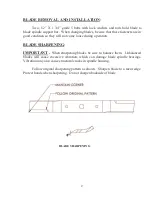
Page 30: ...ill not come loose during operation BLADE SHARPENING IMPORTANT When sharpening blades be sure to balance them Unbalanced blades will cause excessive vibration which can damage blade spindle bearings Vibration may also cause structural cracks in spindle housing Follow original sharpening pattern as shown Sharpen blade to a razor edge Protect hands when sharpening Do not sharpen backside of blade BL...

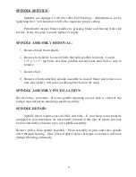
Page 31: ... 4 Remove 4 bolts attaching spindle assembly to mower frame and remove as a unit since pulley will come out through the hole in the deck SPINDLE ASSEMBLY INSTALLATION Reverse above procedure Be sure spindle mounting area of deck is clean of any foreign material before attaching spindle assembly SPINDLE REPAIR Spindle repair requires special skills and tools If your shop is not properly equipped or...

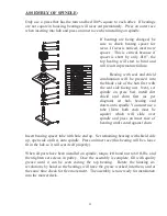
Page 32: ...dirt shield and shim first as per diagram set hub bearing end down onto spindle You must use a tube Note both ends must be square which will slide over spindle and press on inner race of bearing until seated against shim Insert bearing spacer tube with hole end up Set remaining bearing with shield side up open side on first onto spindle Press on inner race this bearing will be a loose fit in the h...

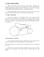
Page 33: ...mental factor in the successful V belt operation Lack of tension will cause slippage and too much tension will cause excessive belt stretch as well as damage to the drive components such as bearings and shafts Therefore to ensure proper belt tension the following procedure is recommended CHECKING BELT TENSION At the mid point of the span apply a deflection force with a spring scale in the directio...

Page 34: ...ends are clean Dirt in the hydraulic system can block the orifice in the line throttle valve or even score the cylinder tubes Hydraulic fluid escaping under pressure has enough force to penetrate the skin Seek medical attention at once if injured by escaping fluid During your daily inspection repair all leaks before they create a major problem Relieve all pressure before working on or disconnectin...

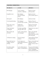
Page 35: ... locks hard to disengage Cylinder not pulling wing up all the way Adjust clevis on end of cylinder Mower deck will not lower Vibration on turning Input shaft does not collapse easily on turning Premature spindle bearing failure Orifice in line throttle valve plugged Draw bar length incorrect Lack of grease at intermediate location of drive shaft Lack of lubrication or grease is contaminated Remove...

Page 36: ...33 ...

Page 37: ...LICS ASSEMBLY 16 DRIVELINE COMPONENTS 18 REAR RIGHT DECK GEARBOX ASSEMBLY 20 LEFT DECK GEARBOX ASSEMBLY 22 4 WAY GEARBOX ASSEMBLY 24 WING DECK PTO SHAFT 26 REAR DECK PTO SHAFT 27 INPUT PTO SHAFT 28 INTERMEDIATE PTO SHAFT 29 TDR 12 FINISHING MOWER PARTS MANUAL TABLE OF CONTENTS Website www progressiveturfequip com Email info progressiveturfequip com ISSUE DATE JAN 2010 ...

Page 38: ...BLADE SPINDLE ASSEMBLY 2 1 2 3 4 6 7 8 9 10 11 12 14 15 17 13 16 5 ...

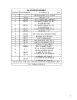
Page 39: ...ADE SPINDLE HOUSING 1 9 524222 BEARING SPACER TUBE 1 10 521701 BOTTOM BEARING 1 11 521305 SHIM WASHER 1 188 9PCS 1 12 521306 SPINDLE DIRT SHIELD 3PCS 1 13 O L 1 4 SQ x 1 9 16 KEY 1 14 524224 TDR 15 BLADE SPINDLE 1 15 O L 1 2 x 1 3 4 GR5 HEX BOLT LOCKWASHER AND NUT 2 16 522615 BLADE KIT 6 L H 3 R H 1 17 524232 COMPLETE BLADE SPINDLE ASSEMBLY 5 9 PULLEY 9 524230 COMPLETE BLADE SPINDLE ASSEMBLY 4 4 P...

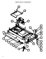
Page 40: ...2 3 4 5 6 8 9 10 11 15 16 17 16 15 18 19 1 22 23 REAR DECK ASSEMBLY 21 20 12 7 14 13 24 4 ...

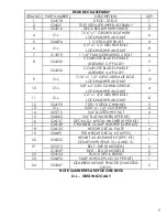
Page 41: ...RIAGE BOLT LOCKWASHER AND NUT 4 11 O L 1 2 x 1 3 4 GR5 HEX BOLT LOCKWASHER AND NUT 8 12 524190 TDR 15 DECK CHANNEL 2 13 O L 5 32 x 1 1 2 COTTER PIN 4 14 305715 3 4 SLOTTED HEX NUT 4 15 526365 3 4 FLAT WASHER 8 PER KIT 1 16 526137 DECK ADJ NYLON WASHER 8 PER KIT 1 17 526148 CHANNEL CLAMP WASHER 4 PER KIT 1 18 526125 HEIGHT DECAL PLATE 4 19 526491 TDR HEIGHT DECAL KIT 6PCS 1 20 526252 HEIGHT ADJUSTM...

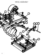
Page 42: ...WING DECK ASSEMBLY 1 2 3 5 6 7 9 8 10 11 12 13 14 15 16 17 16 15 18 19 20 21 22 26 23 24 25 4 6 ...

Page 43: ...L 1 2 x 1 3 4 GR5 HEX BOLT LOCKWASHER AND NUT 8 WING DECK ASSEMBLY LOCKWASHER AND NUT 12 524190 TDR 15 DECK CHANNEL 2 13 O L 5 32 x 1 1 2 COTTER PIN 4 14 305715 3 4 SLOTTED HEX NUT 4 15 526365 3 4 FLAT WASHER 8 PER KIT 1 16 526137 DECK ADJ NYLON WASHER 8 PER KIT 1 17 526148 CHANNEL CLAMP WASHER 4 PER KIT 1 18 526125 HEIGHT DECAL PLATE 4 19 526491 TDR HEIGHT DECAL KIT 6PCS 1 20 526252 HEIGHT ADJUST...

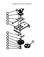
Page 44: ...GEARBOX MOUNT ASSEMBLY 1 3 4 5 6 7 9 10 12 11 8 2 13 8 ...

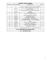
Page 45: ...P BOLT FLATWASHER AND NUT O L 1 5 521019 GEARBOX MOUNT 1 6 521018 STIFFENER NUT BRACKET 2 7 521004 SHIM WASHER 1 250 9PC KIT 1 8 212021 MAIN DRIVE PULLEY 11 1 4 D MODELS ONLY 1 9 521390 KEY 1 4 x 1 5 16 3 PER KIT 1 10 521129 WASHER 3 PC KIT 1 11 O L 3 16 x 1 1 2 COTTER PIN 1 12 521130 CASTLE NUT M24 1 13 521774 MAIN DRIVE PULLEY 8 7 B MODELS ONLY 1 9 GEARBOX MOUNT ASSEMBLY NOTE QUANTITIES ARE FOR ...

Page 46: ...3 2 4 5 13 12 14 15 10 5 16 7 11 WING ASSEMBLY 10 1 11 17 9 3 6 8 7 ...

Page 47: ... L 1 2 X 3 1 2 TAP BOLT FLATWASHER 3 HEX NUTS 2 9 528341 DECK LOCK BRACKET D MODELS ONLY 2 10 O L 3 8 x 2 1 4 BOLT 2 FLAT WASHER AND NUT 2 11 O L 1 4 UNF STRAIGHT GREASE FITTING 6 12 O L 3 8 x 2 BOLT LOCKWASHER AND NUT 4 13 521337 DECK LIFT PIN 4 14 521338 WING SWIVEL PIN 16 3 4 2 15 528210 DECK SWIVEL 2 16 528150 REAR LEFT STANDOFF 1 528144 REAR RIGHT STANDOFF NOT SHOWN 1 17 528112 R H WING 1 11 ...

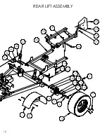
Page 48: ...REAR LIFT ASSEMBLY 12 1 2 3 7 8 6 5 9 10 12 14 13 17 18 16 23 24 19 25 26 27 29 30 31 28 19 15 4 11 20 22 21 ...

Page 49: ...521757 BEARING RACE INNER 2 14 521756 BEARING INSIDE 2 15 521741 GREASE SEAL 2 16 O L 3 8 x 1 1 4 BOLT FLATWASHER AND LOCKNUT 3 17 526445 PULL TUBE FRAME PIN 2 18 528275 DECK STANDOFF BUMPER 2 19 O L 3 8 x 2 BOLT LOCKWASHER AND NUT 4 20 526254 REAR SWIVEL PIN 2 21 O L 1 4 x 1 BOLT LOCKWASHER AND NUT 2 22 524217 SMV BRACKET 1 23 521353 S M V SIGN 1 24 O L 1 4 x 3 4 BOLT LOCKWASHER AND NUT 2 25 5241...

Page 50: ...MAIN FRAME 1 29 3 7 12 11 10 15 16 19 21 20 23 22 26 27 28 33 32 31 30 14 4 5 6 8 9 13 17 18 10 2 24 25 14 ...

Page 51: ...6 17 528182 DECK LOCK D MODELS ONLY 1 18 528184 DECK LOCK MOUNTING BRACKET D MODELS ONLY 1 19 526094 TDR HEIGHT ADJ WRENCH 1 20 528112 R H WING 1 21 521062 S HOOK 1 22 O L 1 4 x 3 4 GR5 CARRIAGE BOLT LOCKWASHER AND NUT 2 23 120519 MANUAL TUBE HOLDER 1 24 528192 FRONT SHIELD MOUNT B D MODELS 1 25 528190 INTERMEDIATE MOUNT 1 26 522413 HOSE GUIDE W HARDWARE 1 27 522308 HOSE SUPPORT SHIELD B MODELS 1 ...

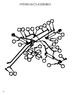
Page 52: ...HYDRAULICS ASSEMBLY 1 2 3 4 5 18 8 9 10 11 14 11 17 16 15 14 13 9 5 12 6 7 6 19 5 10 16 20 ...

Page 53: ...03 WING CYLINDER PIN 3 9 521336 90 DEGREE RESTRICTOR 3 10 521769 HYDRAULIC HOSE 31 2 11 521335 HYDRAULIC HOSE 24 2 12 521345 1 x 3 5 16 PIN 3 13 521427 HYDRAULIC HOSE 52 1 14 521063 HYD ELBOW 45 DEG 3 15 521415 HYDRAULIC HOSE 43 1 16 521770 3 8 TEE 2 17 521416 MALE BRANCH TEE 2 18 O L M12 x 30 BOLT LOCKWASHER 2 19 O L M12 x 40 BOLT LOCKWASHER 2 20 528287 HOSE MOUNT BRACKET 1 17 HYDRAULICS ASSEMBLY...

Page 54: ......

Page 55: ...E PTO SHAFT 1 10 521497 4 WAY GEARBOX 1 11 521033 DECK GEAR BOX LEFT WING DECK 1 12 210061 GEARBOX COUNTER CONE 3 13 O L M8 x 1 25 x 14mm D MODELS 12 14 521718 WING DECK PTO SHAFT 2 15 521197 GEARBOX COVER SPACER 4 16 522463 4 WAY GEARBOX COVER 1 17 O L M12 x 40mm GR 8 8 HEX BOLT 2 18 528287 HOSE MOUNT BRACKET 1 19 O L M12 x 30mm GR 8 8 HEX BOLT LOCKWASHER 2 20 210190 REAR DECK PTO SHAFT 1 21 5210...

Page 56: ...20 DECK GEARBOX REAR DECK AND RIGHT DECK ...

Page 57: ...RING 35 UNI 7435 3PC KIT 1 17 521126 SNAP RING 72 UNI 7437 3PC KIT 1 18 521127 DOUBLE LIP SEAL 35 X 72 X 10 8 1 19 521128 SNAP RING SB72 1 20 521129 WASHER 25 X 44 X 4 3PC KIT 1 21 521130 CASTALATED NUT M24 X 2 1 22 521390 KEY 1 4 X 1 4 X 1 5 16 1 23 521359 SHIM 1 24 521360 SHIM 259 7503 AR 1 25 521361 SPACER RING TAPERED 1 26 521362 BEARING TAPERED 30207A 1 27 521491 SHIM 248 7505 KIT AR 1 28 521...

Page 58: ...22 LEFT DECK GEARBOX ...

Page 59: ...ACER TUBE 1 16 521125 SNAP RING 35 UNI 7435 3PC KIT 1 17 521126 SNAP RING 72 UNI 7437 3PC KIT 1 18 521127 DOUBLE LIP SEAL 35 X 72 X 10 8 1 19 521128 SNAP RING SB72 1 20 521129 WASHER 25 X 44 X 4 3PC KIT 1 21 521130 CASTALATED NUT M24 X 2 1 22 521390 KEY 1 4 X 1 4 X 1 5 16 1 24 521360 SHIM 259 7503 AR 1 25 521361 SPACER RING TAPERED 1 26 521362 BEARING TAPERED 30207A 1 27 521491 SHIM 248 7505 KIT A...

Page 60: ...24 4 WAY GEARBOX ASSEMBLY ...

Page 61: ...BOLT M12 X 40 10 9 2 10 ITEM 20 WASHER BLANK 2 11 521486 THRU SHAFT 1 3 8 X 1 3 8 1 12 521120 OIL SEAL 35 X 52 X 7 2 13 521487 GEAR Z18 M5 3 14 521488 BOLT M12 X 25 8 8 KIT 6 PCS 2 15 521489 OIL LEVEL DIPSTICK 1 16 521796 EXTENSION HOUSING 2 17 521793 GASKET 3 18 521797 COVER 1 19 521491 WASHER SHIM 60 X 72 3 PCS 1 20 522426 BOLT KIT ITEMS 9 2 10 2 1 521497 COMPLETE GEAR BOX 1 25 QUANTITIES ARE FO...

Page 62: ...BE 1 7 521713 INNER TUBE 1 8 521782 ROLL PIN FOR INNER TUBE 1 9 521783 INNER TUBE YOKE 1 10 210017 COLLAR KIT STEEL 1 521727 COLLAR KIT PLASTIC 11 521714 1 2 FEMALE SHAFT WITH SHIELDING 1 12 521715 1 2 MALE SHAFT WITH SHIELDING 1 13 521463 PLASTIC SHIELD BOLT 6PC KIT 6 14 521716 1 2 FEMALE SHIELD WITH LABEL 1 15 521717 1 2 MALE SHIELD 1 16 521467 SAFETY CHAIN 2 17 521455 DANGER LABEL FOR OUTER SHI...

Page 63: ...REAR DECK PTO SHAFT 27 ...

Page 64: ...28 INPUT PTO SHAFT ...

Page 65: ...INPUT PTO SHAFT B MODELS TDR 15 SERIAL 1215102B AND UP TDR 12 SERIAL 1312031B AND UP 29 ...

Page 66: ......

Reviews: