TDR-X
Operator’s Manual
42
SPINDLE ASSEMBLY REPAIR
Note: A video showing this rebuild procedure is available on our website:
http://www.progressiveturfequip.com/service
Spindle repair requires special skills and tools, a shop press is
required. If your shop is not properly equipped or your mechanics
are not properly trained in this type of repair, complete spindle
assemblies are available as service parts.
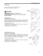
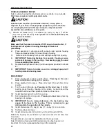
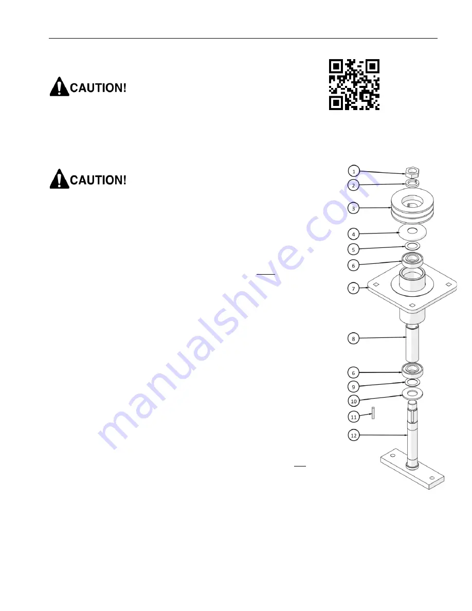
1) Remove LH thread nut (1), lock washer (2), pulley (3), key (11) & shim
(4,5) from spindle assembly.
The spindle nut is left-hand thread, the
pulley has 2 setscrews.
Make sure that the press ram and bed 100% square to each other. If
bearings are not square in housing, bearings will wear out
prematurely.
2)
Place assembly in shop press with support under spindle housing
flange and press spindle (12) down through housing.
3)
Remove bottom bearing from spindle and top bearing from housing
4)
IMPORTANT! Removing bearings from spindle / housing causes
permanent damage to the bearings. New bearings must be used
in re-assembling the spindle
.
5)
Replace bearing spacer tube (8) with new spacer provided in rebuild
kit.
6)
IMPORTANT! Failure to replace a worn or damaged spacer will
lead to premature bearing wear.
REASSEMBLY
7)
Place housing (7) in press (upside down).
Pressing on the outer
race
; install bottom bearing (6) into housing.
8)
Place spindle (12) in press. Place dirt shield (10) and shim (9) on
spindle.
9)
Turn housing right side up
, Pressing on
the
inner race
of bottom
bearing, press housing / bearing on to spindle. A steel tube will be
required to slide over the spindle and press on inner race.
10)
Install bearing spacer (8) with hole end up.
11)
Set top bearing (6) on to spindle.
Pressing on inner race
, press top
bearing on to spindle.
12)
IMPORTANT! Due to design tolerances, the top bearing may
appear to be loose in the housing. This is normal and is not
detrimental to the operation of the spindle.
13)
Install shim washer (5), cap (4), key (11), pulley (3) on to spindle.
14)
Tighten pulley set screws.
15)
Install LH lock washer (2) and LH nut (1) and torque to 60 ft-lb.
Rotate the housing six revolutions by hand and check for smooth, free
movement.
The assembly is now ready for installation into the mower deck.
Note: Orientation of genuine OEM maintenance free bearings are not
important. Do not use greaseable bearings in this assembly.
Summary of Contents for TDR-X
Page 2: ......
Page 48: ...TDR X Operator s Manual 46 ...
Page 54: ...TDR X Parts Manual 2 1 DECK ASSEMBLY 1 1 Blade Spindle Assembly ...
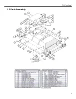
Page 55: ...TDR X Parts Manual 3 1 2 Deck Assembly ...
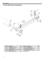
Page 56: ...TDR X Parts Manual 4 1 3 Deck Side Channel Assembly ...
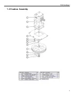
Page 57: ...TDR X Parts Manual 5 1 4 Gearbox Assembly ...
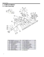
Page 58: ...TDR X Parts Manual 6 2 FRAME ASSEMBLY 2 1 Frame Assembly ...
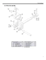
Page 59: ...TDR X Parts Manual 7 2 2 Hitch Assembly ...
Page 60: ...TDR X Parts Manual 8 2 3 Right Wing Assembly ...
Page 61: ...TDR X Parts Manual 9 2 4 Left Wing Assembly ...
Page 62: ...TDR X Parts Manual 10 2 5 Rear Lift Assembly ...
Page 63: ...TDR X Parts Manual 11 2 6 Lock Release Assembly ...
Page 64: ...TDR X Parts Manual 12 2 7 Wheel Assembly ...
Page 65: ...TDR X Parts Manual 13 3 HYDRAULICS ...
Page 66: ...TDR X Parts Manual 14 4 DRIVELINE 4 1 Driveline Layout ...
Page 67: ...TDR X Parts Manual 15 4 2 Input PTO Shaft ...
Page 68: ...TDR X Parts Manual 16 4 3 Intermediate PTO Shaft ...
Page 69: ...TDR X Parts Manual 17 4 4 Wing Deck PTO Shaft ...
Page 70: ...TDR X Parts Manual 18 4 5 Rear Deck PTO Shaft ...
Page 71: ...TDR X Parts Manual 19 4 6 4 Way Gearbox ...

