background image

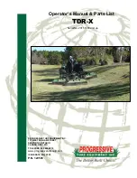
TDR-X 

Operator’s Manual 


INTRODUCTION 

Thank you for purchasing a TDR-X mower. This product is designed and manufactured to allow safe and 
productive mowing of contoured areas. A well-maintained machine will provide years of reliable service.


FOREWORD 

Keep this manual with the mower at all times. This manual is intended as a guide to the  safe use and 
maintenance of the machine, so before you operate this machine, study this manual carefully. 

Replace this manual immediately if it becomes lost. 

This manual is not considered all-inclusive, so for further information on specific components, e.g. PTO 
shafts etc refer to the respective documents included with the manual set for this machine.


The  TDR-X  mower  is  a  contour  roller  turf  grass  finishing  mower  with  a  10.5  foot  cutting  width,  and  is 
designed to be pulled by a 35-40 PTO horsepower utility tractor.  These versatile mowers have the ability 
to mow both contoured and flat terrain that requires a high quality, finished after cut appearance.  High 
blade tip speed leaves a second-to-none after cut appearance. 6-way floating decks, and an Adaptive 
Swivel Hitch isolates the tractor from the mower allowing truer contour tracking. 

Features: 


Three independent floating decks 


Cut height can be set on each deck between 3/8 inch and 3 3/8 inches 


10.5 foot cutting width 


Adaptive Swivel Hitch 


Pro Lift-N-Turn

TM

 allows three decks to be temporarily raised slightly off the ground with the 

PTO still engaged 


Automatic mechanical deck locks for transport  

Applications: 


Golf course roughs, fairways and bunker surrounds 


Corporate and industrial campuses 


Park lands and recreational areas & sports venues 


Landscaped venues 

TDR Series Mower Application Guide 

Model 

TDR-X 

Soil Type 

All (firm 

 sandy) 

Turf Condition 

All conditions 

Comments 

For use in areas where ride-on reel-type mowers cannot be used. 


OSHA Training Requirements (USA) 

The  following  training  requirements  have  been  taken  from  Title  29,  Code  of  Federal  Regulations  Part 
1928.57 (a)(6).  www.osha.gov 

Operator Instructions: At the time of initial assignment and at least annually thereafter, the employer shall 
instruct every employee in the safe operation and servicing of all covered equipment with which he is or 
will be involved, including at least the following safe operating practices. 

In other jurisdictions: 

It  is  good  practice,  following  the  initial  instruction  and  at  least  annually  thereafter,  that  the  employer 
instruct every employee in the safe operation and servicing of all covered equipment with which he is or 
will be involved, including at least the following safe operating practices. 

Summary of Contents for TDR-X

Page 1: ...ual Parts List TDR X Serial No 20111003 and up PROGRESSIVE TURF EQUIPMENT INC 137 WEST WILLIAM STREET SEAFORTH ONTARIO CANADA N0K 1WO TOLL FREE 800 668 8873 www progressiveturfequip com ISSUE DATE May 2020 P N 120596 ...

Page 2: ......

Page 3: ...LIC SYSTEM SERVICE PRECAUTIONS 13 SAFETY DECALS 14 DECAL LISTING 15 ASSEMBLY INSTRUCTIONS 16 INSTALLING DECK PTO SHAFTS 17 MOWER SETUP FOR OPERATION 19 DRAWBAR ADJUSTMENT 19 HITCHING THE MOWER TO THE TRACTOR 20 STOWING THE JACK 20 CONNECTING THE PTO TO THE TRACTOR 20 CONNECTING THE HYDRAULICS 21 CONNECTING THE PULL ROPE 21 MOWER SAFETY LOCKS 21 DECK LOCK SYSTEM 21 TRANSPORT LOCK 22 CHECK PTO LENGT...

Page 4: ...STENER INSTALLATION TORQUE 37 BLADE SERVICING 38 SPINDLE SERVICE 41 HYDRAULICS 43 SUPPORTING MACHINE FOR SERVICE 44 TRANSPORT TIRES 44 LONG TERM STORAGE 44 TROUBLE SHOOTING 45 Si usted No Lee Ingles Pida Ayuda a Alguien Que Se Lo Lea Para Que le Traduzca Las Medidas de Seguridad ...

Page 5: ...independent floating decks Cut height can be set on each deck between 3 8 inch and 3 3 8 inches 10 5 foot cutting width Adaptive Swivel Hitch Pro Lift N TurnTM allows three decks to be temporarily raised slightly off the ground with the PTO still engaged Automatic mechanical deck locks for transport Applications Golf course roughs fairways and bunker surrounds Corporate and industrial campuses Par...

Page 6: ... mower D EU Regulatory Region B Non EU Regulatory Region There are differences in the parts required to service your mower based on this geographic code as are referred to throughout the parts lists Always state this information when contacting your selling dealer and when ordering spare parts REPLACEMENT PARTS INFORMATION Use only Genuine Original Equipment Manufacturers O E M replacement parts T...

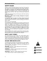
Page 7: ...al MISUSE OF EQUIPMENT It is incumbent upon the user owner and selling dealer of this equipment along with their respective employees to warn and discourage users about the misuse of the equipment whenever knowledge of misuse becomes known whether the act has is or could occur Such acts include but not limited to riding upon use of non OEM parts operation on unstable or dangerous terrain operating...

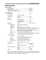
Page 8: ...x 16 3 4 3 per deck or Pro EZII replaceable blade tips Blade Mounting Two bolts nuts per blade No internal threads Rollers Full width heavy wall reinforced ends with HEX drive supported by 2 1 25 hex bearings in ductile iron housing Power Transmission Input Shaft 1 3 8 dia 6 Spline 80 Constant Velocity w auto locking collar Gearbox Cast Iron Housing w Helical gears Deck Drive Fiber reinforced V Be...

Page 9: ...ll three decks all locations The blades are expressed as Left Hand LH and rotate counter clockwise as viewed from the top of the mower WING LIFT CYLINDER BOTH SIDES GEAR BOX ONE EACH DECK HYDRAULIC COUPLERS INPUT PTO SHAFT SWIVEL HITCH PARKING JACK PULL ROPE OPERATOR S MANUAL DECK ROLLER FRONT REAR EACH DECK 4 WAY GEAR BOX WITH COVER HEX ROLLER END BEARING 4 PER DECK INPUT SHAFT SUPPORT HEIGHT of ...

Page 10: ... used it is your responsibility to ensure that it is safe for you and others You should also ensure the machine will not be damaged or made unsafe by the operation maintenance or repair procedures you choose Modifications or adaptations to the machine are not allowed Various jurisdictions have specific requirements for work zone safety Know and adhere to your local requirements Treat the instructi...

Page 11: ...e vests and ear protection are types of equipment that may be required Prolonged exposure to loud noise can cause hearing damage Never operate a mower while under the influence of drugs or alcohol These make reflexes slow and put you and others in grave danger Always make sure you have full concentration while mowing Adhere strictly to all regulations at the worksite pertaining to the operation of...

Page 12: ...er blades can cause severe injury Never tamper with safety devices or operate the mower with them removed Check proper operation regularly Always disengage PTO place all controls in neutral turn power unit off set parking brake and remove key before dismounting for any reason Never place hands or feet under mower deck when the mower is operating or power unit engine is running Disengage the PTO wh...

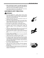
Page 13: ...eriodically check condition of safety devices guards and deflectors Replace only with manufacturer s recommended parts Inspect and replace damaged blades Use only original OEM parts Blades can fail from poor maintenance practices Handle mower blades carefully They are sharp and can cut unprotected skin Use caution and wear gloves when handling them Check to make sure hydraulic hoses are not worn o...

Page 14: ... arc welder ground as close as possible to work area Work with extra care when welding grinding or torch cutting near flammable objects WORKING ON PAINTED SURFACES Heated paint gives off poisonous gases Therefore paint must be removed from an area with a radius of at least 4 in 10 cm before carrying out welding grinding or gas cutting In addition to the health hazard the weld will be of inferior q...

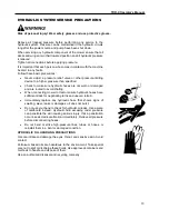
Page 15: ... worn or damaged and are routed to avoid chafing When connecting mower to tractor ensure hydraulic hoses have sufficient slack for negotiating turns and uneven terrain Immediately replace any hydraulic hose that shows signs of swelling wear leaks or damage so it does not burst Do not use your hand to check for hydraulic oil leaks Use a piece of cardboard instead Hydraulic fluid escaping under pres...

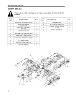
Page 16: ...OGRESSIVE 2 12 PTO READ MANUAL 1 13 SAFETY SIGN OUTER GUARD 4 14 PTO ALIGNMENT 1 ITEM NO DESCRIPTION QTY 1 DANGER READ MANUAL 1 2 WARNING BLADE HARDWARE 1 3 CAUTION REPLACE SHIELDS 8 4 COMPANY NAME 1 5 DANGER BLADE HAZARD 7 6 WARNING OEM PARTS 1 7 CAUTION DISENGAGE PTO 1 8 PTO GREASING 9 NOTICE HITCH SETUP 1 10 MOWER MODEL 2 1 8 3 4 5 9 11 10 6 2 7 12 13 14 ...

Page 17: ...anual 15 DECAL LISTING No 1 209172 No 5 209173 No 3 209113 No 8 526001 No 6 209115 No 7 209174 No 9 521784 No 12 210238 No 13 210237 No 15 521014 PROGRESSIVE No 11 209103 No 4 521817 No 2 209196 No 10 209203 No 14 209189 ...

Page 18: ...mower manual storage tube 4 Place the Input shaft on the provided support 5 Install input shaft clamp yoke on intermediate shaft ensuring gold coloured spacer ring is in place between the input shaft yoke and hanger bearing race 6 Reinstall UNF retaining bolt in input shaft yoke torque to 85 ft lb 7 Reinstall input shaft shield per input shaft service instructions 8 Fasten input shaft guard retain...

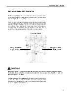
Page 19: ... the yoke laying as flat as possible ie Timed Note it may not be possible to engage the second PTO perfectly aligned to the first due to positioning of the internal gearing Position as close as possible Front of TDR X All PTO shafts have a short chain attached on both ends Find a location to wrap or hook on short chain Be sure that when decks are brought into transport position the safety chain wi...

Page 20: ...ator s Manual 18 TRANSPORT TIRES Check air pressure in the tires and adjust according to specifications Transport Tires 20 PSI The mower is now ready for pre delivery inspection and lubrication prior to first use ...

Page 21: ...uble free hours of operation Incorrect setup may lead to contact between the mower and PTO shaft causing damage to the Input PTO shaft The decal shown in Figure 1 is mounted to the machine and indicates these important hitch dimensions 1 The drawbar length must be adjusted so it is 14 to 15 from the end of the PTO shaft to the center of the draw pin 2 To ensure sufficient clearance the top of the ...

Page 22: ...he tractor 2 Lift input PTO shaft from PTO support ensuring that PTO support swings down and rests on frame tube 3 Slide the mower input shaft locking collar backwards opening the locking mechanism Locking collar should remain in an open position 4 When it is safe to do so hold the PTO against the end of the tractor PTO shaft rotate the PTO by hand until the shaft slides on slightly 5 Slide the yo...

Page 23: ...uring turns CONNECTING THE PULL ROPE The TDR X mower is equipped with a nylon pull rope that is connected to the deck release mechanism that is used for locking decks into transport position Connect it to the tractor in a position that is easily accessible to the operator and will release easily if the mower should ever become disconnected Ensure there is sufficient slack between the tractor and m...

Page 24: ...Lift N Turn system Figure 5 Check each of the three lock arms and release cams making sure they do not bind when the lock release rope is pulled or released Ensure that the lock arms release cams cables and springs are in good condition and move freely Check to see if the lock release pull arm is free to rotate without binding and returns to a neutral position so that the deck lock arms can lay fl...

Page 25: ... very slowly make a sharp turn to the right do not let the CV joint exceed 80 degrees see Figure 7 page 24 2 Watch the PTO shielding to make sure the PTO shaft does not totally collapse There should be a minimum of 5 of the inner black PTO shielding exposed at maximum turn NOTE This is not the worst condition Making turns while the tractor is angling up a hill will cause the PTO shaft to collapse ...

Page 26: ... can occur more easily when turning as you reverse the tractor DISCONNECTING THE MOWER The mower can be stored with the decks in the raised or lowered position If the wings or decks are in the raised position ensure the deck locks are securely engaged before disconnecting the mower from the tractor 1 Place mower on a level surface for storage 2 Ensure that the tractor engine is shut off and the pa...

Page 27: ...d Figure 9 8 Disconnect input shaft guard chain from tractor 9 Slide the mower input shaft locking collar backwards opening the locking mechanism Locking collar should remain in an open position 10 Remove input shaft from tractor collapsing sliding shaft and stow on supplied support bracket Figure 10 11 Remove the tongue jack from the storage location on the left wing and place in the parking posi...

Page 28: ...on the side channels must be loosened When the desired adjustment is made be sure to tighten the locking bolts to maintain the adjusted height The height scales at the back of the deck are set so that the back actually cuts slightly higher this will provide a better cut prolong the life of the blades and reduce horsepower requirement This will also make the side channel look uneven but this is cor...

Page 29: ...not be removed Set mower cutting height to avoid contact 9 Never permit any person other than the operator to ride or board the tractor at any time 10 Check that all lubrication points with grease fittings have been lubricated as per schedule Figure 13 page 31 11 Check the gearbox for possible oil leaks RAISING LOWERING THE WINGS DECKS The mower decks are raised into and from the transport positio...

Page 30: ... rope 4 Set the tractor engine speed just above idle so the engine will not stall after starting the PTO 5 Ensure that everyone is clear of the mower and it is safe to engage the tractor s PTO 6 Engage the tractor PTO 7 Select the proper ground speed gear and slowly engage forward motion 8 Once the mower has come up to speed slowly increase the tractor throttle to required rpm to achieve 540 PTO R...

Page 31: ...r proper float operation 2 Always make sure the locks and lock release cams pivot freely and are in good condition before using this function The mower blades remain at cutting speed while using the Pro Lift N TurnTM system Do not proceed into areas that may have loose debris that may be thrown by the mower blades NOTE The Pro Lift N TurnTM system is designed to be engaged for short durations only...

Page 32: ...perator s manual TRANSPORTING THE MOWER The TDR X mower is NOT designed for use on public roadways Use an appropriate transportation method such as a trailer or float to move mower from site to site if required When transporting the TDR X from site to site ensure the decks are in the raised position and deck safety locks are engaged Use an appropriate sized vehicle to tow the TDR X mower The tongu...

Page 33: ... performing service or maintenance functions When completing a maintenance or service function make sure all safety shields are installed before placing mower in service Maintenance Intervals Service Initial Run 50h Daily Weekly or 50h 100h Monthly 600h Yearly Removal from Storage Grease Intermediate Hanger Bearing X X Locks Lock Release Lock Cams X Deck Pivots Deck Swivels Wings X HEX Roller End ...

Page 34: ...um disulphide additives in the grease2 No synthetic grease3 No High Temperature Grease4 Notes on grease compatibility 1 If a thickener other than lithium is used including lithium complex the existing grease will be contaminated and the lubrication properties may be lost leading to component damage 2 Molybdenum Disulfide Moly is an additive used in slow moving extreme load applications The particl...

Page 35: ...h Monthly 10 Locations Shaft must be disconnected from tractor and collapsed fully for greasing INTERMEDIATE SHAFT 100h Monthly 3 Locations DECK SHAFTS 100h Monthly 7 Locations 3 Shafts CROSS BEARINGS C V CENTER HOUSING C V BALL SOCKET TELESCOPING SHAFT GUARD BUSHINGS CROSS BEARINGS INPUT SPLINE CROSS BEARINGS SLIP YOKE SPLINES GUARD BUSHINGS Inner outer guards must be rotated to align holes for a...

Page 36: ...bolts This is critical for proper function of the Pro Lift N Turn and wing lock system For more information see page 29 2 Have a helper pull and release the pull rope lock release arm and verify that lock release cams move freely If they do not disassemble clean inspect and grease replace bushings if necessary 3 Ensure that the lock arms move freely If they do not move freely disassemble clean ins...

Page 37: ...Yearly The gearbox oil should be changed after the first 50 hours of operation and every 600 hours or yearly afterwards Oil change quantity 1 48 Qt 1 4 Litres DECK GEAR BOX all 3 decks Checking Level 100h Monthly The three deck gear boxes have a combination filler plug and dipstick Remove the plug dry off the dipstick and replace to check oil level It must touch the oil in the gear box Replace oil...

Page 38: ...sting screw 2 Loosen the 4 bolts fastening the gear box slide plate to the mower deck 3 Set desired belt tension by turning the adjusting screw Clock Wise to tighten belts Counter Clock Wise to loosen belts 4 Tighten the 4 bolts fastening the gear box slide plate to the mower deck 5 Tighten jam nut on the adjusting screw 6 Verify proper tension is achieved per V Belt Tension section above CHECKING...

Page 39: ...d in this manual SAE Grade 5 Imperial and Class 8 8 Metric fasteners are to be used in the assembly of this machine unless otherwise specified in this manual Bolt Grade Class Identification SAE Grade 2 SAE Grade 5 SAE Grade 8 Class 8 8 No Dashes 3 Dashes 6 Dashes Metric Bolt Diameter in Recommended Torque in Foot Pounds Newton Meters 5 16 21 28 3 8 38 52 7 16 55 75 1 2 85 115 9 16 125 170 5 8 175 ...

Page 40: ...oys and subjected to rigid heat treat and inspection requirements Substitute blades may not meet these specifications and MAY BE DANGEROUS BLADE SELECTION We offer different blade styles for use with this mower Fixed high lift Combined with Progressive s high tip speed the fixed High Lift blade stands grass blades up for a clean cut even in damp conditions or at high mowing speeds Pro EZII Change ...

Page 41: ... ground out during sharpening Always balance blades before use In abrasive soil conditions monitor condition of the blade wing If erosion of the steel is evident at the base of the wing replace blade PRO EZII BLADE REMOVAL AND INSTALLATION Pro EZII Blade Bar A 1 diameter pilot centers the blade bar on the spindle with two 1 2 grade 5 fasteners When changing blades be sure that pilot is properly se...

Page 42: ... BLADE TIP INSTALLED Grass build up between the tip and blade bar may prevent the tip from pivoting properly at start up or during mowing Ensure all tips are free to rotate prior to operation BLADE SHARPENING Use gloves when handling mower blades Blades can be very sharp IMPORTANT When sharpening blades be sure material removed is equal on both sides of the blade Unbalanced blades will cause exces...

Page 43: ...no tight spots SPINDLE ASSEMBLY REMOVAL 1 Remove blade from spindle 2 Remove belt shield Loosen 4 bolts that hold gearbox slide plate to deck 3 Loosen 1 2 x 3 1 2 tap bolt and slide gearbox toward front until belt is easy to remove as shown in Figure 14 4 Remove belt 5 Remove 4 bolts attaching spindle assembly to mower deck and remove as a unit since pulley will come out through the hole in the de...

Page 44: ...acer tube 8 with new spacer provided in rebuild kit 6 IMPORTANT Failure to replace a worn or damaged spacer will lead to premature bearing wear REASSEMBLY 7 Place housing 7 in press upside down Pressing on the outer race install bottom bearing 6 into housing 8 Place spindle 12 in press Place dirt shield 10 and shim 9 on spindle 9 Turn housing right side up Pressing on the inner race of bottom bear...

Page 45: ...e mower ensure that all decks and wings are in their lowered position and all hydraulic pressure is relieved Pressure can be maintained in the hydraulic circuits long after the power source and pump have been shut down Relieve all pressure before disconnecting hoses or tubes Tighten all connections before applying pressure When connecting the hydraulic couplers to the tractor be sure that both cou...

Page 46: ...ot inflate tires beyond 20 psi NOTE THAT THE TIRES ARE NOT HIGHWAY RATED Mounting and dismounting tires from rims can be dangerous and should be performed by trained personnel using correct tools equipment and procedures LONG TERM STORAGE If the mower is not to be used for an extended period of time 4 months or longer it is recommended that the following maintenance steps are followed 1 Thoroughly...

Page 47: ... shields and clean out all grass Mower Deck will not lower Orifice in cylinder plugged Remove orifice and remove obstruction and reassemble Vibration on turning Drawbar length incorrect Adjust drawbar to specification Damage to intermediate bearing or tractor PTO shaft Input shaft does not collapse easily under power Remove input shaft pull apart and deburr grease splines Grease at proper interval...

Page 48: ...TDR X Operator s Manual 46 ...

Page 49: ...Parts List TDR X Effective serial numbers TDR X 20111003 and up P N 120596 Issue Date May 2020 Si No Lee Ingles Pida Ayuda a Alguien Que Se Lo Lea Para Que le Traduzca Las Medidas de Seguridad ...

Page 50: ...________ Always state this information when contacting your selling dealer and when ordering spare parts Parts Information Use only Genuine Original Equipment Manufacturers O E M replacement parts The use of will fit parts may reduce machine performance void machine warranties and present a safety hazard Use Genuine OEM parts Progressive Turf Equipment Inc 137 West William Street Seaforth Ontario ...

Page 51: ...cks before performing maintenance Block and or support machine using equipment designed for the task When maintaining blades or spindles always ensure locks are seated correctly in place When performing hydraulic maintenance ensure that pressure has been released It is imperative that the operator or qualified service technician reads and understands all the safety information in the Operator s Ma...

Page 52: ...in the assembly shown on that page 3 The Purchase Order must indicate the Name and Address of the person or organization ordering the parts who should be charged and if possible the serial number of the machine for which the parts are being ordered 4 The purchase order must clearly list the quantity of each part the complete and correct part number and the basic name of the part 5 The manufacturer...

Page 53: ...2 1 FRAME ASSEMBLY 6 2 2 HITCH ASSEMBLY 7 2 3 RIGHT WING ASSEMBLY 8 2 4 LEFT WING ASSEMBLY 9 2 5 REAR LIFT ASSEMBLY 10 2 6 LOCK RELEASE ASSEMBLY 11 2 7 WHEEL ASSEMBLY 12 3 HYDRAULICS 13 4 DRIVELINE 14 4 1 DRIVELINE LAYOUT 14 4 2 INPUT PTO SHAFT 15 4 3 INTERMEDIATE PTO SHAFT 16 4 4 WING DECK PTO SHAFT 17 4 5 REAR DECK PTO SHAFT 18 4 6 4 WAY GEARBOX 19 4 7 DECK GEARBOX 20 5 DECALS 21 5 1 SAFETY 21 6...

Page 54: ...TDR X Parts Manual 2 1 DECK ASSEMBLY 1 1 Blade Spindle Assembly ...

Page 55: ...TDR X Parts Manual 3 1 2 Deck Assembly ...

Page 56: ...TDR X Parts Manual 4 1 3 Deck Side Channel Assembly ...

Page 57: ...TDR X Parts Manual 5 1 4 Gearbox Assembly ...

Page 58: ...TDR X Parts Manual 6 2 FRAME ASSEMBLY 2 1 Frame Assembly ...

Page 59: ...TDR X Parts Manual 7 2 2 Hitch Assembly ...

Page 60: ...TDR X Parts Manual 8 2 3 Right Wing Assembly ...

Page 61: ...TDR X Parts Manual 9 2 4 Left Wing Assembly ...

Page 62: ...TDR X Parts Manual 10 2 5 Rear Lift Assembly ...

Page 63: ...TDR X Parts Manual 11 2 6 Lock Release Assembly ...

Page 64: ...TDR X Parts Manual 12 2 7 Wheel Assembly ...

Page 65: ...TDR X Parts Manual 13 3 HYDRAULICS ...

Page 66: ...TDR X Parts Manual 14 4 DRIVELINE 4 1 Driveline Layout ...

Page 67: ...TDR X Parts Manual 15 4 2 Input PTO Shaft ...

Page 68: ...TDR X Parts Manual 16 4 3 Intermediate PTO Shaft ...

Page 69: ...TDR X Parts Manual 17 4 4 Wing Deck PTO Shaft ...

Page 70: ...TDR X Parts Manual 18 4 5 Rear Deck PTO Shaft ...

Page 71: ...TDR X Parts Manual 19 4 6 4 Way Gearbox ...

Page 72: ...TDR X Parts Manual 20 4 7 Deck Gearbox ...

Page 73: ...plete decal kits are also available 521784 DECAL HITCH SETUP 209115 DECAL OEM PARTS 209174 DECAL CAUTION 209113 DECAL REPLACE SHIELDS 521817 DECAL PROGRESSIVE TURF B Models 209175 DECAL GENERAL SAFETY 521817DE DECAL PROGRESSIVE TURF D Models 541503 KIT SAFETY DECALS FOR TDR X 526001 DECAL PTO GREASE 209196 DECAL BLADE HARDWARE 209173 DECAL ROTATING BLADE DANGER ...

Page 74: ...TDR X Parts Manual 22 GREASE POINT DECAL 521014 210238 DECAL CE WARNING GREASE X PER YEAR 209204 209203 TDR X 210237 SAFETY SIGN OUTER GUARD ...

Page 75: ...________________________ __________________________________________________________________________________________ __________________________________________________________________________________________ __________________________________________________________________________________________ __________________________________________________________________________________________ ___________...

Reviews: