TDR-X
Operator’s Manual
36
Figure 14
“V” BELT DRIVE
“V” BELT TENSION:
Proper belt tensioning is a fundamental factor in the successful V-belt operation. Lack of tension will cause slippage,
and too much tension will cause excessive belt stretch as well as damage to the drive components, such as bearings
and shafts. Therefore, to ensure proper belt tension, the following procedure is recommended.
“V” BELT ADJUSTMENT
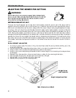
All deck drive belts utilize a threaded adjuster connected through the
deck gear box mount. Tension of both drive belts per deck is set with
one adjustment.
In the event that belt adjustment must be made, follow these steps:
1) Loosen the jam nut on the adjusting screw.
2) Loosen the (4) bolts fastening the gear box slide plate to the
mower deck.
3) Set desired belt tension by turning the adjusting screw:
Clock Wise to tighten belts
Counter Clock Wise to loosen belts
4) Tighten the (4) bolts fastening the gear box slide plate to the
mower deck.
5) Tighten jam nut on the adjusting screw.
6)
Verify proper tension is achieved per “V” Belt Tension section
above.
CHECKING BELT TENSION
At the mid-point of the span, apply a deflection force with a spring scale in the direction perpendicular to the span until
the belt is deflected the 3/8”.
The recommended force to deflect the belt is a minimum of 4.9 lbs. to a maximum of 7.3 lbs.
The first 24 to 48 hours of op
eration is the belt “run in” period. To ensure satisfactory belt performance, belt tension
should be checked during this time period.
(4) Slide
Plate Bolts
Jam Nut
Adjusting
Screw
Summary of Contents for TDR-X
Page 2: ......
Page 48: ...TDR X Operator s Manual 46 ...
Page 54: ...TDR X Parts Manual 2 1 DECK ASSEMBLY 1 1 Blade Spindle Assembly ...
Page 55: ...TDR X Parts Manual 3 1 2 Deck Assembly ...
Page 56: ...TDR X Parts Manual 4 1 3 Deck Side Channel Assembly ...
Page 57: ...TDR X Parts Manual 5 1 4 Gearbox Assembly ...
Page 58: ...TDR X Parts Manual 6 2 FRAME ASSEMBLY 2 1 Frame Assembly ...
Page 59: ...TDR X Parts Manual 7 2 2 Hitch Assembly ...
Page 60: ...TDR X Parts Manual 8 2 3 Right Wing Assembly ...
Page 61: ...TDR X Parts Manual 9 2 4 Left Wing Assembly ...
Page 62: ...TDR X Parts Manual 10 2 5 Rear Lift Assembly ...
Page 63: ...TDR X Parts Manual 11 2 6 Lock Release Assembly ...
Page 64: ...TDR X Parts Manual 12 2 7 Wheel Assembly ...
Page 65: ...TDR X Parts Manual 13 3 HYDRAULICS ...
Page 66: ...TDR X Parts Manual 14 4 DRIVELINE 4 1 Driveline Layout ...
Page 67: ...TDR X Parts Manual 15 4 2 Input PTO Shaft ...
Page 68: ...TDR X Parts Manual 16 4 3 Intermediate PTO Shaft ...
Page 69: ...TDR X Parts Manual 17 4 4 Wing Deck PTO Shaft ...
Page 70: ...TDR X Parts Manual 18 4 5 Rear Deck PTO Shaft ...
Page 71: ...TDR X Parts Manual 19 4 6 4 Way Gearbox ...


