e)
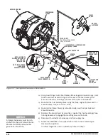
Using a flat head screwdriver hold the valve stem while loosening the coil
nut. Remove the coil.
r)
Loosen and remove the valve stem. Remove the O-ring, plunger and
spring. Save the parts.
g)
Inspect the O-ring and plunger seat for contamination. Clean as
necessary using electrical contact cleaner. Reinstall the valve stem and
O-ring using diesel fuel to lubricate O-ring. DO NOT INSTALL THE
PLUNGER AND SPRING.
h)
Reinstall the coil, coil nut and reconnect the Fuel Solenoid Valve to the
G-II PCM.
i)
Reinstall the burner head by mounting it against the heat exchanger face,
turning clockwise to engage the mounting ears on the bolts.
j)
Reconnect electrical harnesses and fuel supply line.
k)
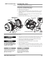
Switch the PROHEAT on and operate for at least one complete cycle.
Observe the operation.
If the PROHEAT runs OK, the Fuel Solenoid Valve is faulty. Go to Fuel
Solenoid Valve replacement.
If a Start diagnostic code is indicated, proceed to Step 6.
Fuel Solenoid Valve replacement:
a)
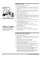
Using a flat head screwdriver, hold the stem in place while loosening the
coil nut. Remove the coil.
b)
Loosen and remove the valve stem. Remove the O-ring, plunger and spring.
c)
Inspect the O-ring and plunger seat in the fuel block for contamination.
Clean as necessary using plastic safe electrical contact cleaner.
d)
Install the new valve stem (with plunger) and seal using a slot screwdriver.
e)
Reinstall the coil, coil nut and reconnect the Fuel Solenoid Valve connector
at the G-II PCM.
f)
Reinstall the burner head by mounting it against the heat exchanger face,
turning clockwise to engage the mounting ears on the bolts.
g)
Reinstall electrical harnesses and fuel supply line.
h)
Switch the PROHEAT on and operate for at least one complete cycle.
Observe the operation.
WARNING
Spilt fuel is flammable.
WARNING
The fuel flow will not be shut off during
cool down (purge). The G-II PCM will
see the flame in cool down (purge)
and after 20 seconds the G-II PCM
will turn off the motor to stop the
flow of fuel and extinguish the flame.
The hot combustion gases can cause
damage to the heater if this test is
preformed repeatedly.
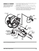
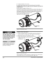
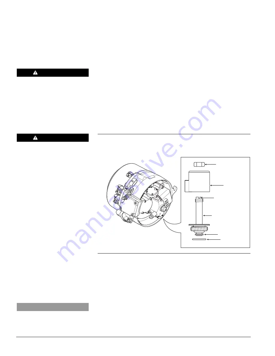
Figure 4-15: Fuel Solenoid Valve Assembly.
COIL
PLUNGER
STEM
TORQUE = 25 in-lbs
±
3 in-lbs (3.4 Nm
±
0.3 Nm)
COIL NUT
TORQUE = 25 in-lbs
±
3 in-lbs (3.4 Nm
±
0.3 Nm)
SCREWDRIVER SLOT
TORQUE = 25 in-lbs
±
3 in-lbs (3.4 Nm
±
0.3 Nm)
NOTICE
All plugs/harnesses must be rein-
stalled into the G-II Proheat Control
Module (G-II PCM) before heater
goes back into service.
O-RING
4-14
PROHEAT M-SERIES G-II PCM SERVICE MANUAL
Summary of Contents for M105 G-II PCM
Page 7: ...PROHEAT M SERIES G II PCM SERVICE MANUAL B 2 ...
Page 11: ...PROHEAT M SERIES G II PCM SERVICE MANUAL D 2 ...
Page 25: ...PROHEAT M SERIES G II PCM SERVICE MANUAL 1 12 ...
Page 35: ...2 10 PROHEAT M SERIES G II PCM SERVICE MANUAL ...
Page 77: ...PROHEAT M SERIES G II PCM SERVICE MANUAL 4 40 ...
Page 89: ...6 2 PROHEAT M SERIES G II PCM SERVICE MANUAL ...


