4-20
PROHEAT M-SERIES G-II PCM SERVICE MANUAL
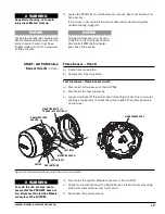
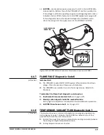
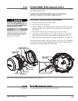
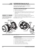
Ignition Module – Check:
a)
Ignition Operation using Ignition mode.
b)
Ignition Electrode check.
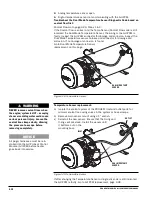
Test Procedure – Ignition Module Spark Check:
a)
Disconnect all harnesses at the G-II PCM.
b)
Disconnect the fuel supply line.
c)
Loosen and back out the Burner Head mounting (2) bolts five to six turns
allowing enough room to rotate the Burner Head 15° counter-clockwise
and remove.
d)
Check Electrodes for carbon bridging and/or damage. Replace if necessary.
e)
Reconnect the power and switch harnesses only.
START: Ignition System
(1 Flash)
WARNING
Shock hazard due to high voltage.
WARNING
To avoid flame DO NOT re-connect
Dual Mode Temperature Sensor
when Burner Head is removed.
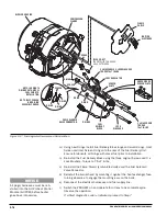
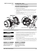
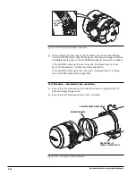
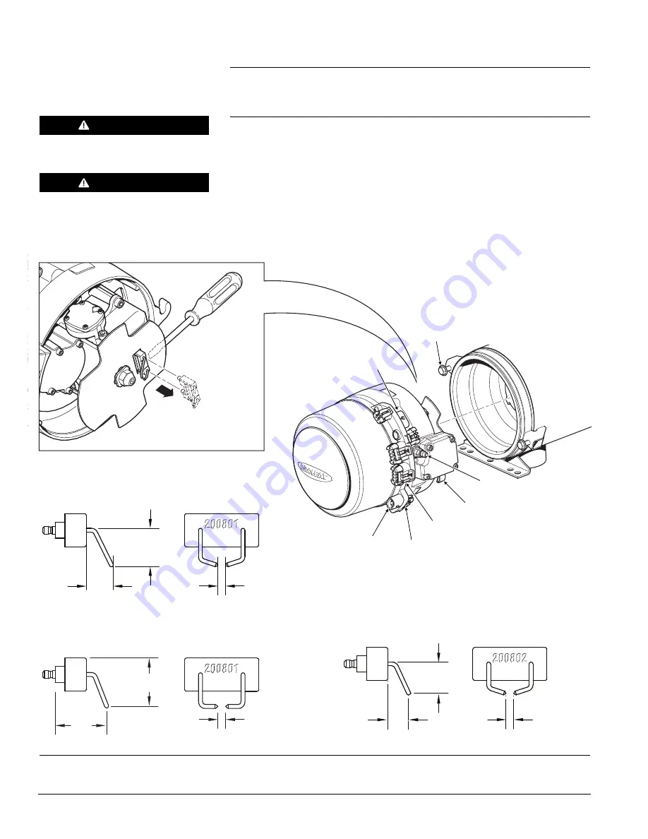
Figure 4-22: Burner Head Removal and Ignition Electrode Removal.
MOUNTING EARS (2)
MOUNTING BOLTS (2)
TORQUE = SEE SECTION 1.3
COOLANT PUMP
SWITCH INPUT
DUAL MODE TEMP
SENSOR
POWER
FUEL INLET
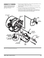
.173" [4.4 mm]
.935"
[23.5 mm]
1.055"
[26.8 mm]
5/32" [4 mm]
3/4"
[19 mm]
5/32" [4 mm]
5/8"
[15.9 mm]
17/32"
[13.5 mm]
13/32" [10.7 mm]
IGNITION ELECTRODE PID# 200801-1
DIAPHRAGM OR ROTARY VANE COMPRESSOR:
500000 – TO DATE
IGNITION ELECTRODE PID# 200801
ROTARY VANE COMPRESSOR:
500000 – 699999
IGNITION ELECTRODE PID# 200802
DIAPHRAGM OR ROTARY VANE COMPRESSOR:
700000 – TO DATE
Summary of Contents for M105 G-II PCM
Page 7: ...PROHEAT M SERIES G II PCM SERVICE MANUAL B 2 ...
Page 11: ...PROHEAT M SERIES G II PCM SERVICE MANUAL D 2 ...
Page 25: ...PROHEAT M SERIES G II PCM SERVICE MANUAL 1 12 ...
Page 35: ...2 10 PROHEAT M SERIES G II PCM SERVICE MANUAL ...
Page 77: ...PROHEAT M SERIES G II PCM SERVICE MANUAL 4 40 ...
Page 89: ...6 2 PROHEAT M SERIES G II PCM SERVICE MANUAL ...


