g) Disconnect the power cable to remove power and stop motor.
h) Disconnect the remote on/off switch.
i)
Reconnect ignition module connector.
j)
Reinstall the clean Fuel Nozzle using diesel fuel to lubricate o-ring.
k) Reinstall air relief (see Section 1.3 for torque).
l)
Reinstall flame shield and electrode.
m) Reinstall the air filter and blower.
n) Reinstall the blower housing.
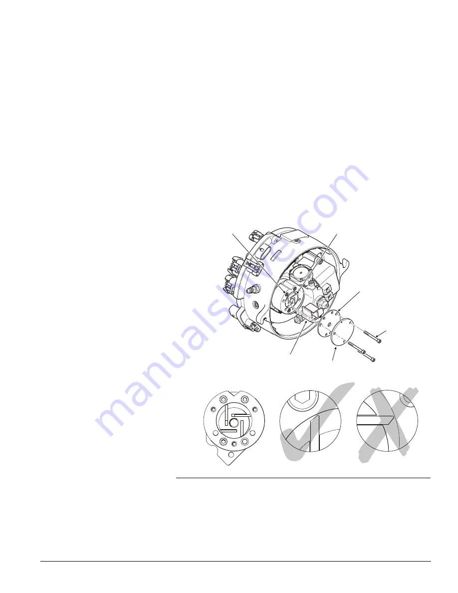
9/64" HEX. HEAD
SCREW (3)
WEAR PLATE
SCREW (3) DO NOT
LOOSEN – SEE NOTICE
BODY BORE & ROTOR
END PLATE
VANES (4)
Figure 5-9: Compressor Components.
3.
Test Air Compressor
a) Test the air pressure setting as shown on page 4-11.
b) If pressure cannot be set correctly, proceed to step 4.
5-9
PROHEAT M-SERIES G-II PCM SERVICE MANUAL
Summary of Contents for M105 G-II PCM
Page 7: ...PROHEAT M SERIES G II PCM SERVICE MANUAL B 2 ...
Page 11: ...PROHEAT M SERIES G II PCM SERVICE MANUAL D 2 ...
Page 25: ...PROHEAT M SERIES G II PCM SERVICE MANUAL 1 12 ...
Page 35: ...2 10 PROHEAT M SERIES G II PCM SERVICE MANUAL ...
Page 77: ...PROHEAT M SERIES G II PCM SERVICE MANUAL 4 40 ...
Page 89: ...6 2 PROHEAT M SERIES G II PCM SERVICE MANUAL ...


