background image

8

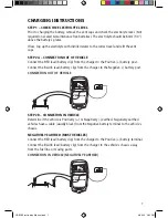
POSITIVELY EARTHED

  Connect the BLACK lead (battery clip) from the charger to the Negative (-) battery terminal.
  Connect the RED lead (battery clip) from the charger to the vehicle’s chassis away from the 

fuel line or moving parts.

  CONNECTION IN VEHICLE (POSITIVELY EARTHED)

STEP 3 – CONNECT TO 240V MAINS POWER

  Ensure ‘CHARGE RATE’ dial is turned to OFF & connect the battery charger to 240V 

mains power.

STEP 4 – SET BATTERY VOLTAGE

  Set the voltage of the battery charger by removing the black terminal cap from either the  

12V or 24V terminal on the top panel of the jumpstarter. Connect the positive battery 
cable via the ring terminal to the appropriate 12V or 24V outlet. Ensure the battery charger 
voltage is set to the same voltage as the battery being charged.

STEP 5 – SET THE CHARGE MODE
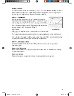
NORMAL CHARGE RATE ADJUSTMENT

  The normal charge rate can be adjusted by turning the ‘CHARGE RATE’ dial on the top 

panel of the unit to setting 1, 2 or 3. The charge rate should be set according to the size 
of the battery.

  See the recommended charge rates for various battery sizes in the table below:

  CHARGE RATE 


BATTERY SIZE


Deep Cycle (Ah) 

Automotive (CCA)   Marine (MCA) 

Time (Hours)

  Setting 1 (12V) 

60–180 

380–1080 

520–1500 

7–24

  Setting 1 (24V) 

75–220 

460–1300 

640–1830 

7–24

  Setting 2 (12V) 

160–460 

670–2800 

1340–3800 

7–24

  Setting 2 (24V) 

190–540 

1130–3240 

1600–4500 

7–24

  Setting 3 (12/24V) 

420–1200 

2500–7200 

3500–1000 

7–24

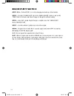
12/24 VOLT 70 AMP BATTERY CHARGER WITH ENGINE START

WORKSHOP 7000

12/24 VOLT 70 AMP BATTERY CHARGER WITH ENGINE START

WORKSHOP 7000

A

FUSE 2 x 100A

POWER ON

3

10

20

30

40

50

60

12V

24V

12/24 VOLT 70 AMP BATTERY CHARGER WITH ENGINE START

WORKSHOP 7000

12/24 VOLT 70 AMP BATTERY CHARGER WITH ENGINE START

WORKSHOP 7000

A

FUSE 2 x 100A

POWER ON

3

10

20

30

40

50

60

12V

24V

12/24 VOLT 70 AMP BATTERY CHARGER WITH ENGINE START

WORKSHOP 7000

12/24 VOLT 70 AMP BATTERY CHARGER WITH ENGINE START

WORKSHOP 7000

A

FUSE 2 x 100A

POWER ON

3

10

20

30

40

50

60

12V

24V

HDBC90 Instruction Manual.indd   8

4/06/12   3:02 PM

Summary of Contents for HDBC90

Page 1: ...12 24V 70A MANUAL P No HDBC90 WORKSHOP BATTERY CHARGER HDBC90 Instruction Manual indd 1 4 06 12 3 02 PM ...

Page 2: ...s is to be in accordance with National wiring rules Do not attempt to charge non rechargeable batteries Never charge a frozen battery If the AC cord is damaged do not attempt to use It must be replaced or repaired by a qualified person Corrosive substances may escape from the battery during charging and damage delicate surfaces Store and charge in a suitable area Ensure all vehicle accessories inc...

Page 3: ... best suit different battery sizes RAPID CHARGE Increases charge rate for a short powerful charge MULTI VOLTAGE OPERATION Suitable for charging 12V 24V batteries 0 60MIN TIMER Automatically turns the battery charger off after a set time when charging your battery in Rapid Charge mode POLARITY PROTECTION Fuse protection prevents damage to the charger in the event of reverse polarity and short circu...

Page 4: ...tting 2 27 0A at 24V setting 2 60 0A at 12V setting 3 60 0A at 24V setting 3 70 0A at 12V rapid charge 70 0A at 24V rapid charge ENGINE START 3 sec on 2 min off 12V 24V 360A at 6V 360A at 12V MINIMUM START 0 0V VOLTAGE BACK DRAIN 12V 24V 5 5mA 11 6mA APPROVALS Electrical Safety EMC HDBC90 Instruction Manual indd 4 4 06 12 3 02 PM ...

Page 5: ...ion Use a Phillips head screw driver to tighten all 4 screws 2 Lay the main body of the battery charger down flat and fit the stabiliser stop to the bottom of the battery charger using the 2 x 50mm self tapping screws provided Use a Phillips head screw driver to tighten screws 3 Place the wheel axle provided through the bottom of the battery charger as per the below illustration 4 Place the 2 x 35...

Page 6: ...let on the top panel of the battery charger via the cable lug on the end of the charging lead To connect both the positive and negative leads to the battery clamps refer to instructions below 1 Slide the rubber cover off the battery clamp handle 2 Loosen the bolt located on the outside of the battery clamp handle using a 10mm socket 3 Feed the bear copper end of the battery clamp lead through the ...

Page 7: ...away from the fuel line or moving parts CONNECTION IN VEHICLE NEGATIVELY EARTHED 12 24 VOLT 70 AMP BATTERY CHARGER WITH ENGINE START WORKSHOP 7000 12 24 VOLT 70 AMP BATTERY CHARGER WITH ENGINE START WORKSHOP 7000 A FUSE 2 x 100A POWER ON 3 10 20 30 40 50 60 12V 24V 12 24 VOLT 70 AMP BATTERY CHARGER WITH ENGINE START WORKSHOP 7000 12 24 VOLT 70 AMP BATTERY CHARGER WITH ENGINE START WORKSHOP 7000 A ...

Page 8: ...STMENT The normal charge rate can be adjusted by turning the CHARGE RATE dial on the top panel of the unit to setting 1 2 or 3 The charge rate should be set according to the size of the battery See the recommended charge rates for various battery sizes in the table below CHARGE RATE BATTERY SIZE Deep Cycle Ah Automotive CCA Marine MCA Time Hours Setting 1 12V 60 180 380 1080 520 1500 7 24 Setting ...

Page 9: ...TEP 7 DISCONNECTION Important Charging will continue until the On Off switch is turned to OFF The battery and charger must be monitored to ensure the battery is not overcharged Once charged the liquid inside the battery may start to boil It is recommended to stop charging when this occurs to prevent damage to the battery STEP 7 DISCONNECTION Turn the CHARGE RATE dial to the OFF position and discon...

Page 10: ...o ENGINE START STEP 7 Turn the vehicle s ignition key to start the engine STEP 8 If engine fails to start after 3 seconds repeat instruction STEP 5 6 before attempting to start the engine again NOTE Do not repeat this operation more than 5 times NOTE When in engine start mode the HDBC90 uses increased power for a short period of time Ensure other appliances connected to that power circuit are turn...

Page 11: ...mp Negative Battery Clamp Trolley Wheels Bottom Stabiliser Stop Charge Meter Charge Engine Start Off Switch Charge Timer Power On Indicator 240V Mains Power Cord 12V 24V Terminals Output Fuse HDBC90 Instruction Manual indd 11 4 06 12 3 02 PM ...

Page 12: ...s located on the top panel of the battery charger To replace blown fuses 1 Disconnect battery charger from 240V mains power 2 Disconnect battery charger leads from the vehicles battery 3 Remove fuse cover on the top panel of the unit 4 Remove and refit fuses Projecta P No HDBCF100A using a 10mm socket 5 Refit fuse cover HDBC90 Instruction Manual indd 12 4 06 12 3 02 PM ...

Page 13: ...some time build up a resistance to being recharged When the charger is first connected these batteries will take a surface charge and the Charge Meter will indicate a fully charged battery within a short while The battery however is not fully charged the charger is voltage sensitive and cannot differentiate between a surface charge and a fully charged battery After a few hours the battery may star...

Page 14: ...minals or a 6 Volt battery has 6 Volts between the positive and negative terminals AMPS The term AMPS is the unit of measure used for current This can be described as the flow of electric charge in a circuit Again if you use the water analogy this would refer to how much water is flowing through the pipe For example if the current is reading 12 Amps then this is the amount of energy going into the...

Page 15: ...15 NOTES HDBC90 Instruction Manual indd 15 4 06 12 3 02 PM ...

Page 16: ...y either BWI or the retailer from where the product was bought in order that the warranty assessment may be performed The consumer must also deliver the original invoice evidencing the date and place of purchase together with an explanation in writing as to the nature of the claim In the event that the claim is determined to be for a minor failure of the product then BWI reserves the right to repa...

Reviews: