13
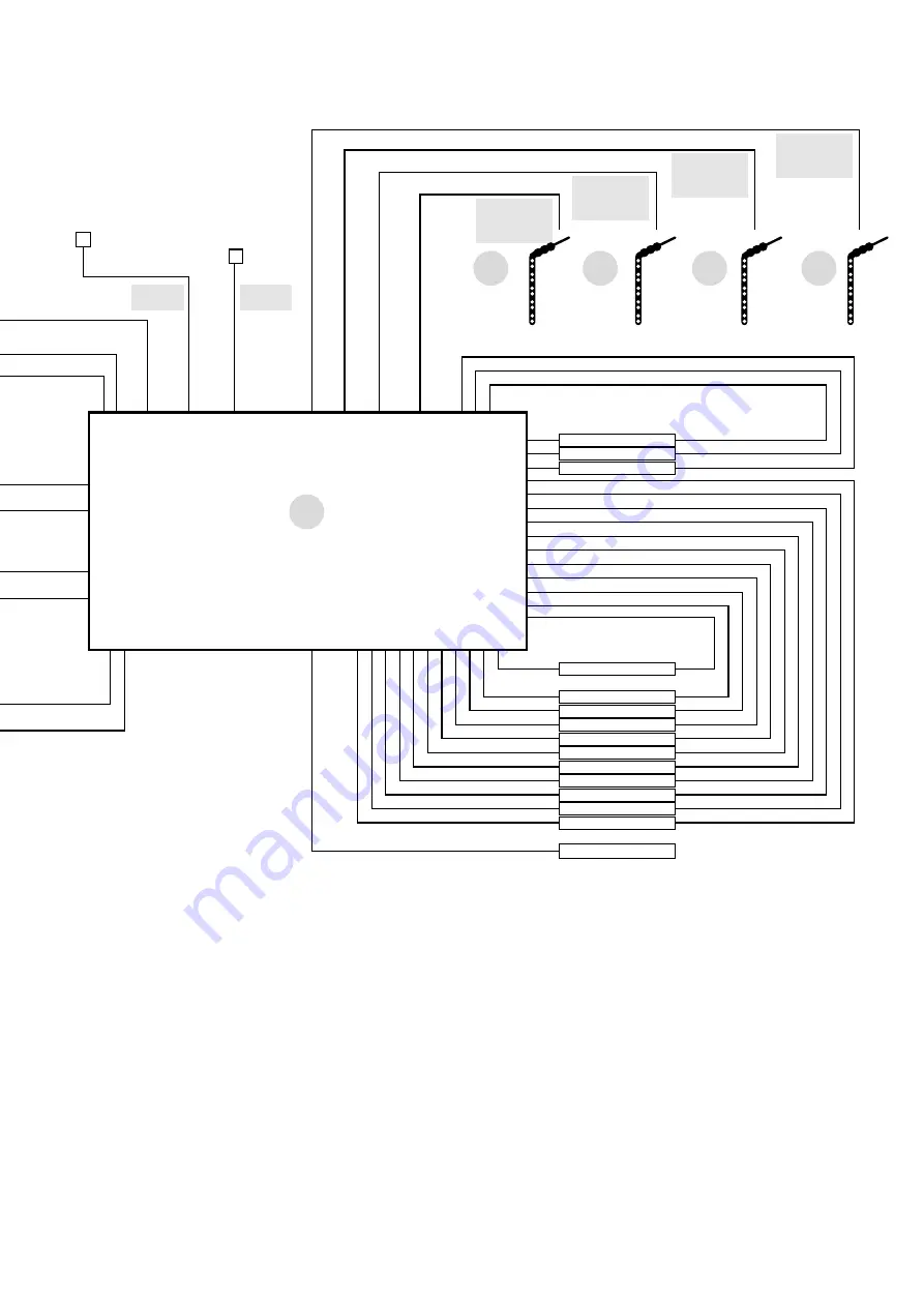
4.2 System Schematic
Figure 17 Installation of PM300-BTJ & PM335J-NODE
1
4
5
6
7
2
PMLCDC
PMAC
PMTS
PMBS
PMWS200/
PMWS400
PMWS200/
PMWS400
PMWS200/
PMWS400
PMWS200/
PMWS400
9
PM335J
Monitor
Solar
Outdoor
Temperature Sensor
Battery Temperature
Sensor and Terminal
Voltage
AC in
240V / 50Hz
~
L
N
BM
COM
House Battery –
House B
House Battery
(12VDC)
Vehicle Battery –
Vehicle B
Vehicle Battery
(12VDC)
Solar–
Solar+
Solar in
Vmp: 17– 50V
Fresh Water
Tank 1
Level Sensor
Fresh Water
Tank 2
Level Sensor
Tap Water
Tank
Level Sensor
Waste Water
Tank
Level Sensor
N L
AC IN
Monitor Switch
Panel
Battery
Sensor
Waste
Water
Tank
Tap
Water
Tank
Fresh
Water
Tank 2
Fresh
Water
Tank 1
•
L12
•
L13
•
L14 L14•
L13•
L12•
L11•
L10•
L9•
L8•
L7•
L6•
L5•
L4•
L3•
L2•
L1•
Solar
• •
Remote
Isolation
Switch
House
Batt -
House
Batt +
Vehicle
Batt -
Vehicle
Batt +
L11 L10 L9 L8 L7 L6 L5 L4 L3 L2 L1
• • • • • • • • • • •
CF / Spare
Awning
Slide Out
Always ON
Spare
Spare
Light 1
Light 2
Light 3
12V
12V
12V
HWS
Pump
PWR Isolation Switch
Summary of Contents for IntelliJay PM300-BTJ
Page 23: ...23 Notes ...


