Installation Guide
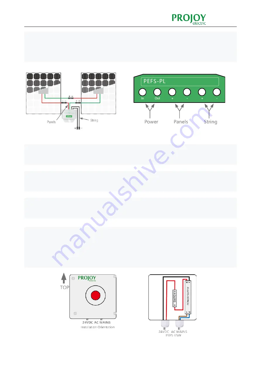
Connect the two PV panels in series (typical wiring example below). Connect the array Positive (+) output
connector to the PEFS-PL Positive (+) input connector. Connect the array Negative (-) output connector to the
PEFS-PL Negative (-) input connector.
Connect the PEFS-PL’s two output cables to the DC isolator/Solar Inverter ensuring that the correct polarity is
maintained throughout the electrical wiring.
When the external power supply is cut off and the emergency switch fails, PFS-PL will be turned off and the pv
module output will be disconnected.
The Emergency Rapid Shutdown Switch Unit PEFS-ESW can be conveniently located anywhere for emergency
access and is supplied with an internal 24VDC power supply to interface with the PEFS-PL units.
Remove the PEFS-ESW cover taking care not to damage the switch or power supply contained within the
PEFS-ESW enclosure. Insert cable glands (supplied) into position, ensuring that the sealing washer (where
supplied) is between the main gland body and the outer enclosure surface, screw the gland into position and
then tighten securing / locking nut.
Summary of Contents for PEFS-PL Series
Page 1: ......
Page 9: ...Installation Guide ...


