background image

Installation Guide                                              

If the connection is to be made through the bottom of PEFS-ESW product, the cable shall be drilled at the 

bottom until the aperture reaches the cable diameter, and there shall be a sealing method to seal the cable with 

the hole drilled at the bottom to ensure that the pfS-ESW product seal can reach IP68. 


Power Supply can be unclipped from the DIN-Rail for easier wiring. 

Connect one lead of the cable to the PEFS-ESW power negative (-) terminal and the other lead to the 24VDC 

positive (+) conductor at the vacant switch terminal. AMP 2 pole socket (internal thread) is used to connect the 

remote end to ensure correct polarity. [AMP connector pin 1 positive (+24VDC), pin 2 negative (0VDC)] 

Do not remove the wire connection between the PEFS-ESW power supply positive pole (+) and the switch. 

Connect the AMP socket (female) of PFS-PL to the AMP plug (male) of PEFS--ESW. 


MULTIPLE INSTALLATIONS 

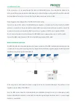
One PEFS-PL will control two solar panels and by series connection of the PEFS, multiple solar panel pairs can be 

connected to form a greater capacity system. The diagram below illustrates a typical example of a PEFS protected 

installation using 8 solar panels and 4 PEFS-PL. 


If the array has an odd number of panels, a single panel can be connected directly to the positive (+) and 

negative (-) panel cables of the PEFS-PL. 


Also, the PEFS series allows for multi-level/multi-zone installation through the use of an Emergency Switch 

Enclosure PEFS-ESW connected in  series with the initial Emergency Rapid Shutdown Switch’s power supply 

Positive (+) wire 24VDC. 

Summary of Contents for PEFS-PL Series

Page 1: ......

Page 2: ...nnections are unsafe and may cause operational problems For the mechanical compatibility of the module converter and PEFS use the same connectors from the same manufacturer on both the PEFS and modules or obtain verification that the connectors to be used are compatible Do not drill through the PEFS PL product as this will damage the PEFS PL component and make it impossible for PEFS PL to work INT...

Page 3: ...it should be mounted within the array boundary of the two panels where the two panels are no greater than 1 foot 30cm apart from each other The installation locations and modes of PFS PL and PEFS ESW are shown below By placing the PEFS PL in position against the underside of the PV panel or the surface where the temperature needs to be sensed Once mounted ensure that the PEFS PL is secure Mounting...

Page 4: ...t off and the emergency switch fails PFS PL will be turned off and the pv module output will be disconnected The Emergency Rapid Shutdown Switch Unit PEFS ESW can be conveniently located anywhere for emergency access and is supplied with an internal 24VDC power supply to interface with the PEFS PL units Remove the PEFS ESW cover taking care not to damage the switch or power supply contained within...

Page 5: ...e 24VDC pin 2 negative 0VDC Do not remove the wire connection between the PEFS ESW power supply positive pole and the switch Connect the AMP socket female of PFS PL to the AMP plug male of PEFS ESW MULTIPLE INSTALLATIONS One PEFS PL will control two solar panels and by series connection of the PEFS multiple solar panel pairs can be connected to form a greater capacity system The diagram below illu...

Page 6: ...sabling the PV module s output Should the detected temperature then drop back to below 85 C the PEFS PL will re engage the PV module s output 2 Manual shutdown Upon the user operating the red push button switch located in the Emergency Switch Enclosure the PEFS PL performs a Rapid Shutdown disabling the PV array output 3 AC Supply Cut Off Shutdown Should there be a necessity by the emergency servi...

Page 7: ...l Cable Length 1200 mm Panel Cable Length 120 mm String Cable Length 1200 mm Standard UL 1741 NEC 2017 690 12 Type PEFS ESW Input Voltage 100 240V AC Rated input current 200mA Vi 115VAC 135mA Vi 230VAC Rated Output Voltage 24V DC Controlled fast shutdown number 20 With Lock Optional Dimensions 125 125 75 mm Ambient Operating Temperature 30 55 Communication GPRS Optional TROUBLESHOOTING Problem Pos...

Page 8: ...S PL input connections Incorrect PEFS PL polarity connection Check PV array Positive goes to PEFS PL Positive and PV array Negative goes to PEFS PL Negative No PEFS PL output Replace PEFS PL PV Inverter input 0V No DC isolator if fitted input Check PEFS PL output connections Check DC inputs to isolator DC Isolator if fitted OFF Turn DC Isolator ON String voltage too low Incorrect PEFS PL polarity ...

Page 9: ...Installation Guide ...

Reviews: