Installation Guide
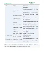
is 0V
(LED OFF)
Check mains ON
Check mains fuse
PEFS-ESW
power supply
failure
Check mains voltage between L & N marked
terminals
Check 24VDC b & - marked terminals
PEFS-ESW
switch activated
Turn red actuator anti-clockwise to release
button
No
PEFS-ESW
switch output
Check 24VDC between switch out terminal &
PSU – marked terminal
Broken cable
Check 24VDC between terminals of remote AMP
Superseal connector (pin 1 +24VDC\pin 2 0VDC)
PV array not connected
Check all PV to PEFS-PL input connections
Incorrect PEFS-PL polarity
connection
Check PV array Positive (+) goes to PEFS-PL
Positive (+)and PV array Negative (-) goes to
PEFS-PL Negative (-)
No PEFS-PL output
Replace PEFS-PL
PV Inverter input 0V
No DC isolator (if fitted)
input
Check PEFS-PL output connections
Check DC inputs to isolator
DC Isolator (if fitted) OFF
Turn DC Isolator ON
String voltage too
low
Incorrect PEFS-PL polarity
connection
Check all PV array Positive (+) go to PEFS-PL
Positive (+)and PV array Negative (-) go to
PEFS-PL Negative (-)
In the occurrence of a fire, PROJOY recommend that all elements of the PEFS Rapid Shutdown system be
assessed for operational suitability by a competent person prior to re-energising.
Summary of Contents for PEFS-PL Series
Page 1: ......
Page 9: ...Installation Guide ...


