background image

www.projoy-electric.com

8


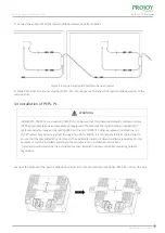
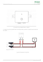
Figure 4.1&4.2 Fixing the Rapid Shutdown Device

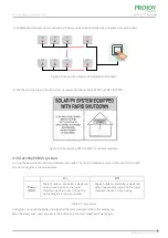
Figure 4.3 Connecting PEFS-PL80P-11 and solar module

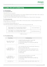
Figure 4.4 Connecting PEFS-PL80P-21 and solar modules

2)  Connect the input of rapid shutdown device to the solar module. 

Panel-level Rapid Shutdown(PLC)

Summary of Contents for PEFS-PL80P-11

Page 1: ...www projoy electric com Installation Guide Panel level Rapid Shutdown PLC ...

Page 2: ...pecification for Product Model 3 3 System Diagram 3 4 Overview and Dimensions of products 3 5 Datasheet 4 Instructions for installation 4 1 Safety Instructions 4 2 Pre installation Check 4 3 Installation of PEFS PL80P 11 21 4 4 Installation of PEFS PLC CN 4 5 Start the PVRSS system 5 System Test and Troubleshooting 5 1 System test 5 1 1 Function test 5 1 2 Maintain test 5 2 Troubleshooting 6 Recycl...

Page 3: ...ully understood all safety regulations contained in this manual can install maintain and repair the Panel level rapid shutdown equipment www projoy electric com 1 DANGER DANGER indicates a hazardous situation which if not avoided will result in death or serious injury WARNING WARNING indicates a hazardous situation which if not avoided can result in death or serious injury or moderate injury CAUTI...

Page 4: ...pid shutdown equipment PVRSE does not perform all of the functions of a complete photovoltaic rapid shutdown system PVRSS This PVRSE must be installed with other equipment to form a complete PVRSS that meets the requirements of NEC NFPA 70 section 690 12 for controlled conductors outside the array Other equipment installed in or on this PV system may adversely affect the operation of the PVRSS It i...

Page 5: ...ead the User Manual first before the installation and operation This device is connected in series to the solar inverter thus all work to the PVRSE shall only be carried out by qualified personnel Danger of hot surface The components inside the PVRSE will release a lot of heat during operation Do not touch the surface during operating RoSH RoSH Directive This device complies the RoSH Directive Panel...

Page 6: ...lication Scope of Products 3 2 Specification for Product Model 3 3 System Diagram 3 Product Information Figure 3 1 System Diagram PEFS PL80P 11 and PEFS PLC CN Figure 3 2 System Diagram PEFS PL80P 21 and PEFS PLC CN Panel level Rapid Shutdown PLC PLC Box Inverter Grid 80V 80V 80V DC DC PEFS PL PEFS PL PEFS PL DC PLC Box Inverter Grid 80V 80V 80V 80V 80V 80V DC DC PEFS PL PEFS PL PEFS PL DC ...

Page 7: ...The dimensions of PEFS PL80P 11 and PEFS PL80P 21 are shown in Figure 3 3 The dimensions of PEFS PLC CN are shown in Figure 3 4 Figure 3 3 Dimensions of PEFS PL80P 11 and PEFS PL80P 21 Figure 3 4 Dimensions of PEFS PLC CN Panel level Rapid Shutdown PLC Unit mm Unit mm ...

Page 8: ... D mm MODEL Operating AC Voltage Range Norminal Frequency Power Consumption DC Input Strings Operating Temperature Range Protection Class Communication Mounting Connector Dimension W H D Weight PEFS PLC CN 100 V 240 V 50 60 Hz 1W 4 Strings 30 to 55 IP65 PLC Wall Mounted MC4 Compatible DC Plug in Connector AC 210mm 174mm 101mm 1800g PEFS PL80P 11 20 80 80 1500 20 PEFS PL80P 21 20 20 80 80 160 1500 ...

Page 9: ...s outside the array Other equipment installed in or on this PV system may adversely affect the operation of the PVRSS It is the responsibility of the installer to ensure that the completed PV system meets the rapid shut down functional requirements This equipment must be installed according to the manufacturer s installation instructions www projoy electric com 7 DANGER NOTICE WARNING To prevent ri...

Page 10: ...4 2 Fixing the Rapid Shutdown Device Figure 4 3 Connecting PEFS PL80P 11 and solar module Figure 4 4 Connecting PEFS PL80P 21 and solar modules 2 Connect the input of rapid shutdown device to the solar module Panel level Rapid Shutdown PLC ...

Page 11: ...the NEC NFPA 70 other equipment installed in or on this PV system may adversely affect the operation of this PVRSS it is the responsibility of the installer to ensure that the completed PV system meets the applicable rapid shut down functional requirements this equipment must be installed according to the manufacturer s installation instructions Installers should determine the installation location...

Page 12: ...to the rapid shutdown controller Then plug each output cable to the solar inverter Figure 4 6 4 7 Fixing the Rapid Shutdown Controller Figure 4 8 Wiring diagram of control box Panel level Rapid Shutdown PLC 1 1 N N N 4 N 6 N 8 N 10 N 20 Solar Inverter PLC Transmitter S1 SN ...

Page 13: ...vices in each string The status of lights is shown as below Rapid shutdown controller is powered off or stop sending signals to the rapid shutdown devices in each string www projoy electric com 11 On Power Red Off Figure 4 10 Connecting PEFS PL80P 21 and solar modules Table 4 1 Light Status 4 5 Start the PVRSS system Panel level Rapid Shutdown PLC 3 Multiple control boxes can be connected in series...

Page 14: ... in 5 1 2 there is something wrong in the DC input of inverter Contact the supplier of inverter 3 Contact Projoy Status light is on DC voltage of inverter is 0V PVRSS doesn t work Status light is on DC voltage of inverter is 0V PVRSS doesn t work Status light is on Description Troubleshooting Table 5 1 System test Please do the function test regularly 1 Push the button of rapid shutdown controller...

Page 15: ...ed to your dealer or you must find an approved collection and recycling facility in your area Within warranty period of the products the invoice and date of purchase are required for the service Besides the trademark on the product should be clearly visible otherwise warranty is not available The product warranty covers all damage caused by design or production However the followings are not covere...

Reviews: