background image

www.projoy-electric.com

RSD PEFS-EL Series

4

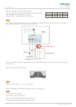
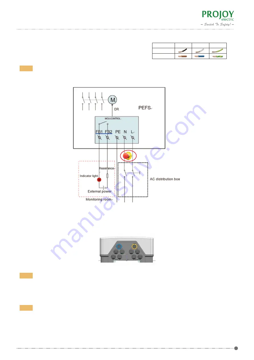
3) Wire the power AC connection to the terminals.

FB1, FB2 are used to remotely display the on and off states of the switch. When the switch is closed, FB1 is connected to 

FB2; when the switch is open, FB1 is disconnected from FB2.

Resistor is selected according to supply voltage, to ensure circuit current less than  the rated current of the Indicator light

 and 

320mA

4) Wire the string cables to the interface.

Please follow the marks (1+, 1-, 2+, 2- ) for PV wiring.

Note!

Note!

 Emergency Button (Optional)

5) Note the installation environment (See the schematic on the next page).

Do not expose to direct sunlight. 

Note!

Do not expose to rain and snow cover.

The installation site must have good ventilation condition.

Do not be in direct contact with (continuous) ingress water.

Wire Color: According to American and Europe standard requirements --

American standard: L

Black

N

White; G

Green

Europe standard: L

Brown

N

Blue; G

Green&Yellow

L

N

G

American

Europe

Summary of Contents for RSD PEFS-EL Series

Page 1: ...www projoy electric com Installation Guide RSD PEFS EL Series...

Page 2: ...evel Rapid Shutdown 1 Scope and General 2 Important Safety Precautions 3 About Rapid Shutdown 4 Operation 5 About PEFS Array level Rapid Shutdown 6 Installation 7 Aftersales service and warranty 8 Con...

Page 3: ...mation of complete disconnection of input power supply Wiring should be done sfter installation of breaker body 2 International Standards IEC 60364 7 712 Electrical installations of buildings Require...

Page 4: ...d create a safe situation When the installation is checked and the PEFS is not affected the PEFS can be switched ON again by removal and re applying the AC voltage to the PEFS The PEFS will also autom...

Page 5: ...core wire MC4 cable 4 8 12 16 20 24 28 32 36 40 1 1 2m for AC power supply 6 Insatllation 6 1 Installation Requirements 6 2 Installation Steps 2 Mount the switch enclosure on the wall Open the box tak...

Page 6: ...ator light and 320mA 4 Wire the string cables to the interface Please follow the marks 1 1 2 2 for PV wiring Note Note Emergency Button Optional 5 Note the installation environment See the schematic o...

Page 7: ...switches on AC POWER ON Approx 35 sec 2 Step 2 Wait one minute UPS is charging Approx 1 min 6 Diagram 1 10 strings Distribution box Firefighter Safety Switch Inverter Grid PV Arrays PV Arrays PV Array...

Page 8: ...fter the repair make a paid repair otherwise it can be replaced with a paid 7 1 Warranty On the premise of user s compliance with reservation and use specifications of the breaker for breakers whose d...

Reviews: