


Montageanleitung /
Installation manual
MBN GmbH
Balthasar-Schaller-Str. 3
86316 Friedberg
Germany
www.proled.com
4.
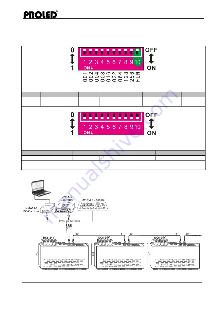
Testing Functions
1. Automatic Funktions
As diagram, FUN=ON: test function; 1-9DIP switch=OFF: BLACK
DIP 1
DIP 2
DIP 3
DIP 4
DIP 5
DIP 6
DIP 7
DIP 8
DIP 9
RED
GREEN
BLUE
YELLOW PURPURE
CYAN
WHITE
SCAN
Color
gradual
DIP8/DIP9 at “ON” is changing mode. 1-7 is to realize 8 speed levels. 7 is the fastest levels while dip
switch 1-7=OFF: the speed is 0.
DIP 1
DIP 2
DIP 3
DIP 4
DIP 5
DIP 6
DIP 7
Speed 1
Speed 2
Speed 3
Speed 4
Speed 5
Speed 6
Speed 7
As diagram, when several dip switches are on, subjected to the highest switch value, when all the
dip switches=ON, it's the color gradual in the test mode, 7 speed level
5. Conjuction Diagramm
The PROLED DMX PWM DIMMER 24-CHANNEL
can be worked with any brand of DMX console.
This connection diagram is an example of the
DMX PC console, DMX controller, the DMX
manual console and the DMX decoder.
PROLED DMX PWM DIMMER 24-CHANNEL is
equipped with two types DMX terminal for the
user’s selection. This connection diagram is the
example of the XRL-3 terminal, and user can also
use green terminal.


