background image

ECLIPSEFS

2

SAFETY

General instruction

•  The products referred to in this manual conform to the European Community Directives and are there-

fore marked with 

 and approved for the North American Market. 

•  The unit is supplied with hazardous network voltage (230V~). Leave servicing to skilled personnel only. 

Never make any modifications on the unit not described in this instruction manual, otherwise you will 

risk an electric shock.

•  Connection must be made to a power supply system fitted with efficient earthing (Class I appliance ac-

cording to standard EN 60598-1). It is, moreover, recommended to protect the supply lines of the units 

from indirect contact and/or shorting to earth by using appropriately sized residual current devices.

•  The connection to the main network of electric distribution must be carried out by a qualified electrical 

installer. Check that the main frequency and voltage correspond to those for which the unit is designed 

as given on the electrical data label. 

•  This unit is not for home use, only professional applications.

•  Never use the fixture under the following conditions:

- in places wet;

- in places subject to vibrations or bumps;

- in places with a temperature of over 45 °C.

•  Make certain that no inflammable liquids, water or metal objects enter the fixture.

•  Do not dismantle or modify the fixture.

•  All work must always be carried out by qualified technical personnel. Contact the nearest sales point for 

an inspection or contact the manufacturer directly.

•  If the unit is to be put out of operation definitively, take it to a local recycling 

plant for a disposal which is not harmful to the environment.

Warnings and installation precautions

•  If this device will be operated in any way different to the one described in this manual, it may suffer 

damage and the guarantee becomes void. Furthermore, any other operation may lead to dangers like 

short circuit, burns, electric shock, etc.

•  Before starting any maintenance work or cleaning the projector, cut off power from the main supply.

•  Always additionally secure the projector with the safety rope. When carrying out any work, always com-

ply scrupulously with all the regulations (particularly regarding safety) currently in force in the country 

in which the fixture’s being used.  

•  Install the fixture in a well ventilated place.

•  Keep any inflammable material at a safe distance from the fixture.

•  Shields, lenses or ultraviolet screens shall be changed if they have become damaged to such an extent 

that their effectiveness is impaired.

•  The lamp (LED) shall be changed if it has become damaged or thermally deformed.

•  Never look directly at the light beam. Please note that fast changes in lighting, e. g. flashing light, may 

trigger epileptic seizures in photosensitive persons or persons with epilepsy.

•  Do not touch the product’s housing when operating because it may be very hot.

•  This product was designed and built strictly for the use indicated in this documentation. Any other use, 

not expressly indicated here, could compromise the good condition/operation of the product and/or 

be a source of danger.

•  We decline any liability deriving from improper use of the product.

WARNING! Before carrying out any operations with the unit, carefully read this instruction 
manual and keep it with cure for future reference. It contains important information about 
the installation, usage and maintenance of the unit.

Summary of Contents for ECLIPSEFS

Page 1: ...ECLIPSEFS OPTIC 14 19 26 36 50 USER MANUAL ECLIPSEFS EN LED PROFILER ...

Page 2: ...y any means for any commercial use In order to improve the quality of products PROLIGHTS reserves the right to modify the characteristics stated in this instruction manual at any time and without prior notice All revisions and updates are available in the manuals section on site www prolightsamerica com ...

Page 3: ...ture 3 4 Static mode 3 4 Static mode 3 5 Linking 3 5 Linking 3 6 DMX configuration 3 6 DMX configuration 3 7 DMX mode 3 7 DMX mode 3 8 Fixture ID and RDM 3 8 Fixture ID and RDM 3 9 Connection of the DMX line 3 9 Connection of the DMX line 3 10 Construction of the DMX termination 3 10 Construction of the DMX termination 3 11 DMX control 3 11 DMX control 3 12 Setup 3 12 Setup 3 13 Avanced 3 13 Avanc...

Page 4: ...al which is not harmful to the environment Warnings and installation precautions If this device will be operated in any way different to the one described in this manual it may suffer damage and the guarantee becomes void Furthermore any other operation may lead to dangers like short circuit burns electric shock etc Before starting any maintenance work or cleaning the projector cut off power from ...

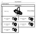
Page 5: ...3 ECLIPSEFS 1 INTRODUCTION 1 1 TECHNICAL DRAWING Technical drawing Fig 1 259 4mm 10 21mm 268 8mm 10 58in 663 3mm 26 11in ECLIPSEFS OPTIC ...

Page 6: ...or Housing Middle part compatible with 14 19 26 36 50 optics 2 Optics for ECLIPSE profiler 14 beam Optics for ECLIPSE profiler 19 beam Optics for ECLIPSE profiler 26 beam Optics for ECLIPSE profiler 36 beam Optics for ECLIPSE profiler 50 beam ECLIPSEFS OR ...

Page 7: ...t of breakage always replace the fuse with the same type and rating 11 CONTROL PANEL with display and 4 button used to access the control panel functions and manage them 12 POWER OUT PowerCON OUT connect to supply power to the next unit 13 POWER IN PowerCON IN for connection to a socket 100 240V 50 60Hz via the supplied mains cable 14 DMX OUT 5 pole XLR 1 ground 2 DMX 3 DMX 4 N C 5 N C 15 DMX IN 5...

Page 8: ...stallation always comply scrupulously with all the regulations particularly re garding safety currently in force in the country in which the fixture s being used Install the projector at a suitable location by means of the mounting bracket 1 Always additionally secure the projector with the safety rope from falling down For this purpose fas ten the safety rope at a suitable position so that the ma...

Page 9: ...o a socket which can be switched on and off via a light switch 3 2 BASIC Access control panel functions using the four panel buttons located directly underneath the LCD Display fig 4 MODE ESC UP DOWN ENTER Used to access the menu or to return a previous menu option Navigates downwards through the menu list and increases the numeric value when in a function Navigates upwards through the menu list a...

Page 10: ...rature C F Fahrenheit Celsius Default Celsius MaxTemp 60 90 C 140 194 C Default 90 C Screen ð Backlight ð Off 99m Default 02m Flip Display ð Yes No Default No Fixture ð Fan mode ð Auto Speed High Speed Default Auto Speed Hibernation Disable Min 1 99 Default Disable Theatre Yes No Default No LED frequency ð 600Hz 1200Hz Default 1200Hz Adjust ð Dimmer 3 ADVANCED ð Dimmer ð OFF Dimmer 1 Default Dimme...

Page 11: ...eive Slave Receive Presets ð Master Alone DMX Color MIX ð Master Alone DMX Presets ð All Red Green Blue Lime Cyan Magenta Yellow Orange LightY Light B Light P 2700K 3200K 4200K 5000K 5500K 6000K 7000K 8000K 9000K 10000K Tungsten ð Red Green Blue Lime Color Mix 1 ð Switch HoldTime FadeTime Dimmer ð On Off Default On Color Mix 16 ð Switch HoldTime FadeTime Dimmer ð On Off Default On ...

Page 12: ...ECLIPSEFS 10 6 DEFAULT ð Basic Reload ð On Off Program Reload ð On Off Password Private Reload Recover calibration and RDM PID code ð On Off All Reload Recover calibration and RDM PID code ð On Off ...

Page 13: ...ese will be played in sequence Tungsten Allow to choose the maximum value that each color must have when the 1 ch Tungsten mode is used Press the ENTER button to confirm your choice Press the MODE button to go back or to meet the waiting time to exit the setup menu 3 5 LINKING 1 Connect the DMX OUT of the master unit via 5 pole XLR cable to the DMX IN of the first slave unit 2 Connect the DMX OUT ...

Page 14: ...the connections The RDM data is transmitted via the standard XLR poles 1and 2 new DMX cables are not necessary RDM ready and conventional DMX devices can be operated in one DMX line The RDM protocol sends own packages in the DMX512 data feed and does not influence conventional devices If DMX splitters are used and RDM control is to be used these splitters must sup port RDM The number and type of R...

Page 15: ...f the first unit Connect the DMX output to the DMX input of the following unit Connect again the output to the input of the following unit until all the units are connected in chain When the signal cable has to run longer distance is recommended to insert a DMX termination on the last unit 3 10 CONSTRUCTION OF THE DMX TERMINATION The termination avoids the risk of DMX 512 signals being reflected b...

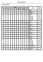
Page 16: ...ne CTC Fine 000 255 2 1 1 2 2 3 Red Red 0 100 000 255 4 Red fine Red fine 0 100 000 255 3 2 2 3 3 5 Green Green 0 100 000 255 6 Green fine Green Fine 0 100 000 255 4 3 3 4 4 7 Blue Blue 0 100 000 255 8 Blue fine Blue Fine 0 100 000 255 5 4 5 5 9 Lime Lime 0 100 000 255 10 Lime fine Lime Fine 0 100 000 255 6 11 CTC Preset No function 2000K 2700K 2700K 3200K 3200K 4200K 4200K 5600K 5600K 8000K 8000K...

Page 17: ...u can set using the arrow buttons To have the display or set a value of Off 99 min to turn off the display after the amount of time you choose Flip Display Orientation of the display This function allows you to rotate the display 180 to get a better view of the display when the unit is hanging upside down Select Yes to activate or No to dis able this function Press the ENTER button to confirm your...

Page 18: ...roposed Code CHxx and press the ENTER button to confirm the setting Press the MODE button to go back and save changes 3 14 FIXTURE INFORMATION To view all the information on the device proceed as follows Press the button MODE so many times until the display shows INFORMATION then press the button EN TER Press the UP DOWN button to scroll through the menu then select one of the following informatio...

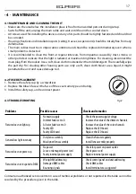
Page 19: ...netrate the unit and cause damage to it 4 2 FUSE REPLACEMENT 1 Remove the safety cap by a screwdriver 2 Replace the blown fuse with a fuse of the exact same type and rating 3 Install the safety cap and reconnect power 4 3 TROUBLESHOOTING Fig 8 Problems Possible causes Checks and remedies Fixture does not light up No mains supply Dimmer fader set to 0 All color faders set to 0 Faulty LED Faulty LED...

Page 20: ......

Reviews: