5
ECLJRG2
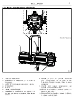
Rear panel
1.3 OPERATING ELEMENTS AND CONNECTIONS
Fig.2
1. MOUNTING BRACKET
2. LOCKING KNOB for the mounting bracket
3. SAFETY EYE to attach safety cable
4. SHUTTER
5. OPTICS
6. FILTER FRAME
7. CONTROL PANEL with display and 4 button
used to access the control panel functions
and manage them.
8. POWER IN mains plug for connection
to a socket (100-240V~/50-60Hz) via the
supplied mains cable.
9. POWER OUT: connect to supply power to the
next unit.
10. DMX IN (5-pole XLR): 1 = ground, 2 = DMX -, 3
= DMX +, 4 N/C, 5 N/C.
11. DMX OUT (5-pole XLR): 1 = ground, 2 = DMX-,
3 = DMX+, 4 N/C, 5 N/C.
4
1
3
6
5
2
7
11
9
10
8
Summary of Contents for ECLJRG2
Page 1: ...USER MANUAL MANUALE UTENTE EN IT LED PROFILER ECLJRG2 ...
Page 30: ......
Page 31: ......


