background image

PARCOLOR6168

2

WARNING! Before carrying out any operations with the unit, carefully read this instruction 

manual and keep it with cure for future reference. It contains important information about the 

installation, usage and maintenance of the unit.

SAFETY

General instructions

•  The products referred to in this manual conform to the European Community Directives and are therefore marked with  .

•  The unit is supplied with hazardous network voltage (230V~). Leave servicing to skilled personnel only. Never make 

any modifications on the unit not described in this instruction manual, otherwise you will risk an electric shock.

•  Connection must be made to a power supply system fitted with efficient earthing (Class I appliance according to 

standard EN 60598-1). It is, moreover, recommended to protect the supply lines of the units from indirect contact and/

or shorting to earth by using appropriately sized residual current devices.

•  The connection to the main network of electric distribution must be carried out by a qualified electrical installer. Check that 

the main frequency and voltage correspond to those for which the unit is designed as given on the electrical data label. 

•  This unit is not for home use, only professional applications.

•  Never use the fixture under the following conditions:

- in places subject to vibrations or bumps;

- in places with a temperature of over 45°C or less than 2°C.

•  Make certain that no inflammable liquids, water or metal objects enter the fixture.

•  Do not dismantle or modify the fixture.

•  All work must always be carried out by qualified technical personnel. Contact the nearest sales point for an inspection 

or contact the manufacturer directly.

•  If the unit is to be put out of operation definitively, take it to a local recycling 

plant for a disposal which is not harmful to the environment.

Warnings and installation precautions

•  Never look directly at the light beam. Please note that fast changes in lighting, e. g. flashing light, may trigger epileptic 

seizures in photosensitive persons or persons with epilepsy. 

•  Before starting any maintenance work or cleaning the projector, cut off power from the main supply. 

•  Make certain that the fixture is off and the temperature of the components cannot cause burns. 

•  Always additionally secure the projector with the safety rope. When carrying out any work, always comply scrupu-

lously with all the regulations (particularly regarding safety) currently in force in the country in which the fixture’s 

being used. 

•  Avoid blocking air intakes and outputs.

•  Keep any inflammable material at a safe distance from the fixture.

•  The lamp (LED) shall be changed if it has become damaged or thermally deformed.

GENERAL INFORMATION

Shipments and claims

The goods are sold “ex works” and always travel at the risk and danger of the distributor. Eventual damage will have to be 

claimed to the freight forwarder. Any claim for broken packs will have to be forwarded within 8 days from the reception 

of the goods.

Warranty and returns

The guarantee covers the fixture in compliance with existing regulations. You can find the full version of the “General 

Guarantee Conditions” on our web site www.musiclights.it. Please remember to register the piece of equipment soon 

after you purchase it, logging on www.musiclights.it. The product can be also registered filling in and sending the form 

available on your guarantee certificate. For all purposes, the validity of the guarantee is endorsed solely on presentation 

of the guarantee certificate. Music & Lights will verify the validity of the claim through examination of the defect in rela-

tion to proper use and the actual validity of the guarantee. Music & Lights will eventually provide replacement or repair of 

the products declining, however, any obligation of compensation for direct or indirect damage resulting from faultiness.

The information provided in this manual has been carefully checked.

However Music & Lights S.r.l. is not responsible for any possible inaccuracy.

Summary of Contents for PARCOLOR6168

Page 1: ...I GB Manuale Utente User Manual PARCOLOR6168 LED PARCAN PROJECTOR ...

Page 2: ...REV 002 12 10 ...

Page 3: ... e specifiche tecniche 1 1 Elementi di comando e collegamenti 1 2 Descrizione 1 3 Specifiche tecniche 2 Installazione 2 1 Montaggio 3 Funzioni e impostazioni 3 1 Funzionamento 3 2 Funzionamento in modalità manuale 3 3 Funzionamento tramite unità di controllo DMX 3 4 Collegamenti della linea DMX 3 5 Costruzione del terminatore DMX 3 6 Impostazione dell indirizzo di start 3 7 Tabella canali DMX 4 Ma...

Page 4: ... unità togliere la tensione dalla rete di alimenta zione Assicurarsi che l unità sia spenta e che la temperatura delle parti non possa provocare ustioni È assolutamente necessario proteggere l unità per mezzo di una fune di sicurezza Nell eseguire qualsiasi intervento attenersi scrupolosamente a tutte le normative in materia di sicurezza vigenti nel paese di utilizzo Evitare di ostruire l ingresso...

Page 5: ...i montaggio 2 Manopola di fissaggio per la staffa di montaggio 3 COPERCHIO del proiettore 4 DMX OUT XLR a 3 poli 1 massa 2 DMX 3 DMX 5 DMX IN XLR a 3 poli 1 massa 2 DMX 3 DMX 6 FUSIBILE 250V2A 7 DIP SWITCH 8 CAVO DI ALIMENTAZIONE PARCOLOR 6168 4 5 7 6 Fig 1 8 1 3 2 PANNELLO DI CONTROLLO VISTA LATERALE ...

Page 6: ...ni di colori per possibilità cromatiche illimitate angolo di proiezione 15 Funzionamento ed elettronica 4 canali DMX per controllo professionale o semplificato Dimmer Strobe RGB passaggio lineare stepless dei valori sui canali DMX Modalità manuale con selezione dei valori e dei programmi tramite dip switch automatica con esecu zione dei programmi preimpostati Master Slave con più unità collegate F...

Page 7: ...10 volte il peso dell unità Fissare il proiettore attraverso l apposita staffa 1 ad una collocazione idonea È assolutamente necessario assicurare il proiettore contro la caduta utilizzando un cavo di sicurezza in particolare collegare il cavo in un punto adatto in modo che la caduta del proiettore non possa superare i 20 cm Orientare il proiettore intervenendo se necessario sulla manopola della st...

Page 8: ...tà con una presa comandata da un interruttore 3 2 Funzionamento in modalità manuale Disponendo tutti i DIP switch fig 3 in posizione OFF si attiva la modalità manuale Con i DIP switch si pos sono scegliere separatamente i LED per rosso verde e blu Fig 3 Impostazione del modo Manuale Le combinazioni di effetti possibili sono elencate nella seguente tabella Switches set to ON Function 1 SOFT RED 2 R...

Page 9: ...on è in grado di trasmettere in modo affidabile i dati di controllo DMX Collegare l uscita DMX del controller con l ingresso DMX della prima unità Collegare quindi l uscita DMX con l ingresso DMX della successiva unità l uscita di quest ultima con l ingresso di quella successiva e via dicendo finchè tutte le unità sono collegate formando una catena Per installazioni in cui il cavo di segnale deve ...

Page 10: ...ossimo indirizzo di start possibile per unità n 3 4 33 33 36 37 42 46 L indirizzo di start viene impostato come numero binario per mezzo dei DIP switch n 1 9 Quindi risulta dall addizione dei valori dei DIP switches posizionati su ON Esempi per gli indirizzi 1 6 e 104 Per poter comandare il PARCOLOR6168 con un unità di comando luce occorre impostare l indirizzo di start DMX per il primo canale DMX...

Page 11: ...ffitto truss sospensioni devono essere total mente esenti da qualsiasi deformazione I cavi di alimentazione devono essere in condizione impeccabile e devono essere sostituiti immediata mente nel momento in cui anche un piccolo problema viene rilevato L interno del dispositivo deve essere pulito ogni anno utilizzando un aspirapolvere o un getto d aria Si dovrebbe procedere ad intervalli regolari al...

Page 12: ......

Page 13: ...ption and technical specifications 1 1 Operating elements and connections 1 2 Description 1 3 Technical specifications 2 Installation 2 1 Mounting 3 Functions and settings 3 1 Operation 3 2 Operation in manual mode 3 3 Operation via a light control unit 3 4 Connection of the DMX line 3 5 Construction of the DMX termination 3 6 Adjusting the start address 3 7 DMX control 4 Maintenance 4 1 Cleaning ...

Page 14: ...he light beam Please note that fast changes in lighting e g flashing light may trigger epileptic seizures in photosensitive persons or persons with epilepsy Before starting any maintenance work or cleaning the projector cut off power from the main supply Make certain that the fixture is off and the temperature of the components cannot cause burns Always additionally secure the projector with the s...

Page 15: ... and connections 1 MOUNTING BRACKET 2 Locking knob for the mounting bracket 3 Projector back cover 4 DMX OUT 3 pole XLR 1 ground 2 DMX 3 DMX 5 DMX IN 3 pole XLR 1 ground 2 DMX 3 DMX 6 FUSE 250V2A 7 DIP SWITCH 8 POWER CORD PARCOLOR 6168 4 5 7 6 Fig 1 8 1 3 2 CONTROL PANEL SIDE VIEW ...

Page 16: ...wer consumption than traditional lamps Color synthesis RGB Colour mixing 16million colours for a limitless colour range High efficiency precise optics Projection angle 15 LEDs average life span 75 000 hours Electronics and features 4 DMX Channel mode for professional or simplified Dimmer Strobe RGB control Manual control of values and programs through the LED display menu Linear and stepless trans...

Page 17: ...to support a weight of 10 times of the unit s weight Install the projector at a suitable location by means of the mounting bracket 1 Always additionally secure the projector with the safety rope from falling down For this purpose fasten the safety rope at a suitable position so that the maximum fall of the projector will be 20 cm Adjust the projector and use the knob 2 to slightly release or tight...

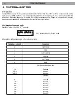
Page 18: ...nvenient operation it is recommended to connect the unit to a socket which can be switched on and off via a light switch 3 2 Operation in manual mode Set all DIP switch fig 3 to OFF position Fig 3 Adjustment of the Manual mode All possible configurations are in the following table Switches set to ON Function 1 SOFT RED 2 RED 3 SOFT GREEN 4 GREEN 5 SOFT BLUE 6 BLUE 3 9 1 3 9 2 3 9 SLOW COLOR CHANGI...

Page 19: ... the use of balanced microphone cable is not recommended because it cannot trans mit control DMX data reliably Connect the controller DMX input to the DMX output of the first unit Connect the DMX output to the DMX input of the following unit Connect again the output to the input of the following unit until all the units are connected in chain When the signal cable has to run longer distance is rec...

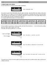
Page 20: ...ss 104 switches Nos 7 6 and 4 set to ON The easiest way is to start from the highest possible place value and to add the smaller values until the start address will result The start address is adjusted as a binary number with the DIP switches Nos 1 9 2 It will result by adding the place values of the switches set to ON Examples with the start addresses 1 6 and 104 Numberof DMXchannels Start addres...

Page 21: ...blem is detected In order to protect the device from overheating the ventilation openings should be cleaned monthly The interior of the device should be cleaned annually using a vacuum cleaner or air jet It is recommended to clean the front at regular intervals from impurities caused by dust smoke or other particles to ensure that the light is radiated at maximum brightness For cleaning disconnect...

Page 22: ......

Page 23: ...chi conseguenti sono a carico del possessore dell apparecchio A tutti gli effetti la validità della garanzia è avallata unicamente dalla presentazione del certificato di garanzia The guarantee covers the unit in compliance with existing regulations You can find the full version of the General Guarantee Conditions on our web site www musiclights it Abstract General Guarantee Conditions Please remem...

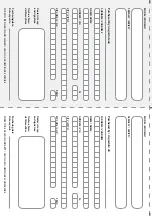
Page 24: ...date Data acquisto FORM TO BE FILLED IN AND MAILED CEDOLA DA COMPILARE E SPEDIRE FORM TO BE FILLED IN AND KEPT CEDOLA DA COMPILARE E CONSERVARE PROV ZIP CODE C A P MODEL MODELLO SERIAL N SERIE N Purchased by Acquistato da SURNAME COGNOME Dealer s stamp and signature Timbro e firma del Rivenditore NAME NOME ADDRESS VIA N CITY CITTA Purchasing date Data acquisto PROV ZIP CODE C A P ...

Page 25: ......

Page 26: ......

Page 27: ......

Page 28: ... Music Lights S r l PROLIGHTS is a brand of Music Lights S r l company Via Appia km 136 200 04020 Itri LT ITALY tel 39 0771 72190 fax 39 0771 721955 www musiclights it info musiclights it Music Lights S r l entertainment technologies ISO 9001 2008 Certified Company ...

Reviews: