background image

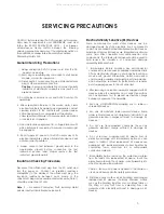
CAUTION : Before servicing the DVD covered by this service 

Electrostatically Sensitive (ES) Devices

data and its supplements and ADDENDUMS, read and 

Some semiconductor (solid state) devices can be 

follow the 

SAFETY PRECAUTIONS NOTE 

: if unforeseen 

damaged easily by static electricity. Such components 

circumstances create conflict between the following 

commonly are called Electrostatically Sensitive (ES) Devices. 

servicing precautions and any of the safety precautions in 

Examples of typical ES devices are integrated circuits and 

this publications, always follow the safety Precautions.

some field effect transistors and semiconductor chip 

Remember Safety First:

components. The following techniques should be used to 
help reduce the incidence of component damage 
caused by static electricity. 

General Servicing Precautions

1. Immediately before handling any emiconductor 

1. Always unplug the DVD DC power cord from the DC 

component or semiconductor-equipped assembly, drain 

power source before:

off any electrostatic charge on your body by touching a 

(1) Removing or reinstalling any component, circuit board, 

known earth ground. Alternatively, obtain and wear a 

module, or any other assembly.

commercially available discharging wrist strap device, 

(2) Disconnection or reconnecting any internal electrical 

which should be removed for potential shock reasons 

plug or other electrical connection.

prior to applying power to the unit under test. 

    Caution : 

A wrong part substitution or incorrect polarity 

installation of electrolytic capacitors may result in an 

2. After removing an electrical assembly equipped with ES 

explosion hazard.

devices, place the assembly on a conductive surface 
such as aluminum toil, to prevent electrostatic charge 

2. Do not spray chemicals on or near this DVD or any of its 

buildup or exposure of the assembly.

assemblies.

3. Use only a GROUNDED-tip soldering iron to solder or 

3. Unless specified otherwise in this service data, clean 

unsolder ES devices.

electrical contacts by applying an appropriate contact 
cleaning solution to the contacts with a pipe cleaner, 

4. Use only an anti-static solder removal device. Some 

cotton-tipped swab, or comparable soft applicator.

solder removal devices not classified a "anti-static" can 

Unless specified otherwise in this service data, lubrication 

generate electrical charges sufficient to damage ES 

of contacts is not required.

devices.

4. Do not defeat any plug/socket B+ voltage interlocks with 

5. Do not use freon-propelled chemicals. These can 

which instruments covered by this service manual might 

generate electrical charge sufficient to damage ES 

be equipped.

devices.

5. Do not apply AC power to this DVD and/or any of its 

6. Do not remove a replacement ES device from its 

electrical assemblies unless all solid-state device heat 

protective package until immediately before you are 

sinks are correctly installed

ready to install it. (Most replacement ES devices are 

.

packaged with leads electrically shorted together by 

6. Always connect test instrument ground lead to the 

conductive foam, aluminum foil, or comparable 

appropriate ground before connection the test 

conductive material.)

instrument positive lead. Always remove the test  
instrument ground lead last.

7. Immediately before removing the protective material 

from the leads of a replacement ES device, touch the 
protective material to the chassis or circuit assembly into 

Insulation Checking Procedure

which the device will be installed.

Disconnect the attachment plug trom the AC outlet and 

Caution : Be sure no power is applied to the chassis or 

turn the power on. Connect an insulation resistance 

circuit, and observe all other safety precautions. 

meter(500V) to the blades of the attachment plug. The 
insulation resistance between each blade of the 

8. Minimize bodily motions when handling unpackaged 

attachment plug and accessible conductive parts (Note 1) 

replacement ES devices. (Normally harmless motion 

should be more than 1M ohm.

such as the brushing together of your clothes fabric or 
the lifting of your foot from a carpeted floor can 

Note 1 : 

Accessible Conductive Parts including Metal 

generate static electricity sufficient to damage an ES 

panels, input terminals, Earphone jacks, etc. 

device.)

SERVICING PRECAUTIONS

3

All manuals and user guides at all-guides.com

Summary of Contents for DVD-557

Page 1: ...dity 45 80 R H Atmos phere pres s ure 860mbar 1060mbar TABLE OF CONTE NTS 1 GE NE R AL___________________________________________ 2 3 2 BLOCK DIAGR AM_____________________________________ 4 5 3 E LE CTR ICAL TR OUBLE S HOOTING GUIDE ________________ 6 21 4 PR INTE D CIR CUIT_____________________________________ 22 28 5 E LE CTR ICAL PAR TS LIS T____________________________ 29 40 1 All manuals and ...

Page 2: ...E OR A RESISTOR RATED AT 1 WATT OR MORE LEAD TENSION AROUND PROTRUDING METAL SURFACES MUST BE 2 USE ONLY RECOMMENDED FACTORY REPLACEMENT TUBES AVOIDED SUBJECT TIPS ON PROPER INSTALLATION 6 ALL CRITICAL COMPONENTS SUCH AS FUSES FLAMEPROOF RESISTORS CAPACITORS ETC MUST BE REPLACED WITH EXACT FACTORY TYPES DO NOT USE REPLACEMENT COMPONENTS OTHER THAN THOSE SPECIFIED OR MAKE UNRECOMMENDED CIRCUIT 1 NE...

Page 3: ...on to the contacts with a pipe cleaner 4 Use only an anti static solder removal device Some cotton tipped swab or comparable soft applicator solder removal devices not classified a anti static can Unless specified otherwise in this service data lubrication generate electrical charges sufficient to damage ES of contacts is not required devices 4 Do not defeat any plug socket B voltage interlocks wi...

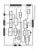
Page 4: ...R EEPROM W29C011AP 15 16MSDRAM HY57V16160DTC 16MSDRAM HY57V16160DTC 8MFLASH CS4340 AUDIO DAC CN202 1 10 5V 5V 5V DGND DGND DGND DGND 12V SLOAD SLOAD CN203 1 10 20 AGND AGND SW1 SW2 SW4 6 SW3 STB DATA CLK MPEG_CMD L R PARKING AGND AGND AGND AGND MIC_ON AGND AIN AGND VD AGND AMUTE 1 CVBS1 CVBS2 SPDIF VGND VGND DGND CN204 U9 U10 U1 U8 U7 SST39VF800 U12 U502 TO MAIN BOARD TO MAIN BOARD SERVO AND DECOD...

Page 5: ...P CONT AUTO CONT ACC B 1 10 1 10 BUS B AGND ACC NC R CH L CH VM1 DGND DGND DGND 1 FRONT L FRONT R AGND AGND AGND SBW CN601 REAR L REAR R AGND AGND CN604 TLC2272 U604 U701 Pt2257 U706 TLC2272 U101 TC9257F U102 FAE347 A28 U707 LC72722M TO KEY BOARD TO SERVO AND DECODER BORAD TO SERVO AND DECODER BORAD OPERATIONAL AMPLIFIER POWER AMPLIFIER SOUND FADER CONTROL 8BIT MCU U203 MOTOR DIRVER TUNER RECEIVER...

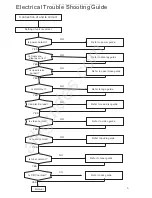
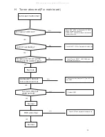
Page 6: ... video normal Normal Refer to power guide Refer to display guide Refer to open close guide Refer to read disc guide Refer to video guide Refer to audio guide NO YES YES YES YES YES YES NO NO NO NO NO Is LOGOout Refer to logo guide YES NO Is tuner normal Refer to tuner guide YES NO Is CDC normal Refer to cdc guide YES NO 6 All manuals and user guides at all guides com a l l g u i d e s c o m ...

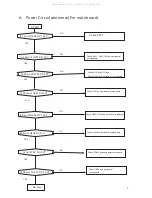
Page 7: ...l YES NO Check Q401 U403 L401and peripheral components Check U201 and peripheral components Check Q404 Q408 and peripheral components Check U404 and peripheral components Check ZD439 and peripheral components Check U402 and peripheral components YES YES YES YES YES NO NO NO NO NO NO Is 26pin of U201 DC 5V Check Zd401 and peripheral components NO YES Check ACC and ACC fuse 7 All manuals and user gu...

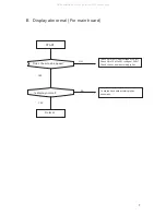
Page 8: ... Is display normal Normal Check if pin14 of CN201voltage of DC 8V Check if pin 16 of 201 voltage of DC5V Check the key board according to key schematic Cn Check the key board according to key schematic YES NO YES NO 8 All manuals and user guides at all guides com ...

Page 9: ...1641 DC 4 6V after eject key being pressed Is voltage between 2 and 1pin of cn7 at S D board DC 4 5V Check R205 R245 L201 2 Check Zd201 Lb1641 Check connection between main board and S D board 1 Check cn8 at S D board connection between it and MCU Normal YES YES YES NO NO NO 9 All manuals and user guides at all guides com ...

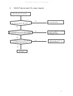
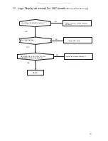
Page 10: ...tage for CN202 normal No Logo display Having picture no color or color disappered during playback Check Connection of Main board and S D board Change S D board Check decoder part and change Y1 Normal YES NO YES NO YES NO 10 All manuals and user guides at all guides com ...

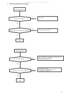
Page 11: ...s laser normal Does the disc turn Can TOC be read Refer to Focus abnormal Refer to laser abnormal Refer to disc turn abnormal Refer to TOC abnormal Normal YES YES YES YES NO NO NO NO 11 All manuals and user guides at all guides com a l l g u i d e s c o m ...

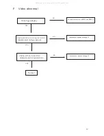
Page 12: ...r disappeared during playback Having picture but picture disappeared during playback Check the connection of M5705 and Zr36748 Check decoder part and change Y2 Check decoder part and change Y2 Normal YES YES YES NO NO NO 12 All manuals and user guides at all guides com ...

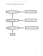
Page 13: ...l normal Is the front channel and sbw channel normal Is the power amplifier normal Normal Refer to rear out abnormal Refer to front out abnormal YES YES YES NO NO NO Check U301 and peripheral components 13 All manuals and user guides at all guides com ...

Page 14: ...bnormal Normal Check P9V if P9V is 9V check Q110 Q115 and peripheral components If P9V is 0V check according to main board power schematic Check Tc9257 X101 and peripheral components Check 17pin of Tc9257 Q103 Q108 and peripheral components Check connection between 16 17pin of U101 and U503 Replace U503 Check U707 and peripheral components YES YES YES YES YES YES NO NO NO NO NO NO 14 All manuals a...

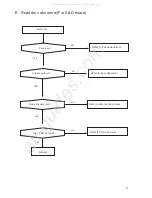
Page 15: ...CDC audio abnormal Is 1 7pin of U501 normal Is 3 4 29 30pin of U503 normal Normal Is pin8 of U501 Dc9 If not check correlative printed wire else check peripheral components If still abnormal change U501 Check U503 and peripheral components Is 31pin of U503 DC9V If still abnormal change U503 YES YES YES YES NO NO NO NO 15 All manuals and user guides at all guides com ...

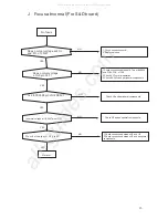
Page 16: ...5954 and FCS FCS of CN2 2 Check if Y3 normal operation 3 Check BA5954 and peripheral components 1 Check connection between U2 and U9 2 Check connection between U2 and peripheral components Check U2 and peripheral components Is 28 30 35 58pin of U2 DC5V Is normal voltage at 18 26 27pin of U2 Check U3 and peripheral components YES YES YES YES YES NO NO NO NO NO 16 All manuals and user guides at all ...

Page 17: ... 22pin of U2 Does normal Voltage at cathode of D2 D3 Normal YES YES YES 1 Check connections between M5705 and Sp3721 2 check Sp3721 and peripheral components Check Sp3721 and peripheral components YES Check Q1 Q2 and peripheral components Change pick up 17 All manuals and user guides at all guides com ...

Page 18: ...eck if voltage of 13 9 pin of u2 is normal Normal Check connection of mechanism Check connections between Ba 5954 and CN6 check Ba5954 and peripheral components Check connections between Sp3721 pin 26 and Ba5954 pin 4 27 Check Sp3721 and peripheral components Check connections between U2 5 23 pins and U1 pins 13 9 Check U1 and peripheral components YES YES YES YES NO NO NO NO 18 All manuals and us...

Page 19: ...FIN at 2 pin of U1 Normal Refer to laser guide Check slide motor and connections to decoder board 1 Check connections between 11 13 pin of U2 and 13pin of CN2 2 Check 12 14pin of U2 and 15pin of CN2 3 Replace pickup 1 Check connection between U1 and U2 2 Check U2 and peripheral components YES YES YES NO NO NO 19 All manuals and user guides at all guides com ...

Page 20: ...bnormal Is the 1 7 pin of U604 abnormal Is mute control normal Normal Check connections between Main board and S D board Check connections between CN603 and U603 Check U604 and peripheral components Check Q605 Q607 Q609 Q610 and peripheral components YES YES YES YES YES NO NO NO NO 20 All manuals and user guides at all guides com ...

Page 21: ...ormal Is mute control normal Normal Check connection between CN603 and U503 Check U503 and peripheral components Check U701 and peripheral components Check U706 and peripheral components Check Q602 Q610 Q620 Q603 Q702 Q701 and peripheral components YES YES YES YES NO NO NO NO 21 All manuals and user guides at all guides com a l l g u i d e s c o m ...

Page 22: ...22 All manuals and user guides at all guides com ...

Page 23: ...23 All manuals and user guides at all guides com ...

Page 24: ...72 J0 FA Resistor chip 4K7 5 1 16W R20 2 R41B 0103 J0 FA Resistor chip 10K 5 1 16W R205 2 R41B 0102 J0 FA Resistor chip 1K 5 1 16W R206 2 R41B 0102 J0 FA Resistor chip 1K 5 1 16W R21 2 R41B 0100 J0 FA Resistor chip 10 5 1 16W R208 2 R41B 0103 J0 FA Resistor chip 10K 5 1 16W R22 2 R41B 0100 J0 FA Resistor chip 10 5 1 16W R23 2 R41B 0100 J0 FA Resistor chip 10 5 1 16W R24 2 R41B 0391 J0 FA Resistor ...

Page 25: ... 4376 00 0A KTC4376 NPN Q5 2 T20C 3904 00 0A 2N3094 PNP Q9 2 T20C 3904 00 0A 2N3094 PNP Q707 2 T20C 3904 00 0A 2N3094 PNP CHIP NETWORK RES RN1 2 R81B 0470 J0 FA SRN 47 5 1 16W RN2 2 R81B 0330 J0 FA SRN 33 5 1 16W RN7 2 R81B 0103 J0 FA SRN1 0K 5 1 16W RN8 2 R81B 0103 J0 FA SRN 10K 5 1 16W RN9 2 R81B 0103 J0 FA SRN 10K 5 1 16W RN10 2 R81B 0103 J0 FA SRN 10K 5 1 16W RN11 2 R81B 0103 J0 FA SRN 10K 5 1...

Page 26: ... C15B 0103 K0 WA Capacitor Chip 0 01uF 16V 10 C203 2 C15B 0103 K0 WA Capacitor Chip 0 01uF 16V 10 C204 2 C15B 0103 K0 WA Capacitor Chip 0 01uF 16V 10 C205 2 C15B 0103 K0 WA Capacitor Chip 0 01uF 16V 10 C206 2 C15B 0103 K0 WA Capacitor Chip 0 01uF 16V 10 C209 2 C15B 0103 K0 WA Capacitor Chip 0 01uF 16V 10 C210 2 C15B 0103 K0 WA Capacitor Chip 0 01uF 16V 10 C211 2 C15B 0224 N0 YA Capacitor Chip 0 22...

Page 27: ...1uF 16V 80 20 C450 2 C15B 0471 K0 WA Capacitor Chip 470pF 16V 10 C451 2 C15B 0103 K0 WA Capacitor Chip 0 01uF 16V 10 C452 2 C15B 0103 K0 WA Capacitor Chip 0 01uF 16V 10 C453 2 C15B 0103 K0 WA Capacitor Chip 0 01uF 16V 10 C454 2 C15B 0103 K0 WA Capacitor Chip 0 01uF 16V 10 C455 2 C15B 0103 K0 WA Capacitor Chip 0 01uF 16V 10 C462 2 C15B 0471 K0 WA Capacitor Chip 470pF 16V 10 C490 2 C15B 0103 K0 WA C...

Page 28: ... 2 C15B 0103 K0 WA Capacitor Chip 0 01uF 16V 10 C702 2 C252 0106 M0 0D Electrolytic CAP 10uF 16V 20 C720 2 C15B 0103 K0 WA Capacitor Chip 0 01uF 16V 10 C724 2 C252 0106 M0 0D Electrolytic CAP 10uF 16V 20 C725 2 C259 0227 M0 0D Electrolytic CAP 220uF 16V 20 C726 2 C252 0106 M0 0D Electrolytic CAP 10uF 16V 20 C728 2 C15B 0224 N0 YA Capacitor Chip 0 22uF 16V 80 20 C729 2 C15B 0682 K0 WA Capacitor Chi...

Page 29: ... 1 16W R261 2 R46X 0103 J0 FA Resistor chip 10KΩ 5 1 2W R262 2 R41B 0473 J0 FA Resistor chip 47KΩ 5 1 16W R303 2 R41B 0203 J0 FA Resistor chip 20KΩ 5 1 16W R314 2 R41B 0473 J0 FA Resistor chip 47KΩ 5 1 16W R332 2 R41B 0273 J0 FA Resistor chip 27KΩ 5 1 16W R333 2 R41B 0473 J0 FA Resistor chip 47KΩ 5 1 16W R334 2 R41B 0102 J0 FA Resistor chip 1KΩ 5 1 16W R335 2 R41B 0102 J0 FA Resistor chip 1KΩ 5 1 ...

Page 30: ... 16W R613 2 R41B 0472 J0 FA Resistor chip 4 7KΩ 5 1 16W R616 2 R41B 0303 J0 FA Resistor chip 30KΩ 5 1 16W R617 2 R41B 0103 J0 FA Resistor chip 10KΩ 5 1 16W R618 2 R41B 0392 J0 FA Resistor chip 3 9KΩ 5 1 16W R619 2 R41B 0471 J0 FA Resistor chip 470Ω 5 1 16W R621 2 R41B 0392 J0 FA Resistor chip 3 9KΩ 5 1 16W R622 2 R41B 0303 J0 FA Resistor chip 30KΩ 5 1 16W R623 2 R41B 0471 J0 FA Resistor chip 470Ω ...

Page 31: ...MHz 600Ω FB4 2 L60B 0601 00 0A Impedance at 100MHz 600Ω FB5 2 L60B 0601 00 0A Impedance at 100MHz 600Ω FB203 2 L60B 0601 00 0A Impedance at 100MHz 600Ω FB204 2 L60B 0601 00 0A Impedance at 100MHz 600Ω FB205 2 L60B 0601 00 0A Impedance at 100MHz 600Ω FB206 2 L60B 0601 00 0A Impedance at 100MHz 600Ω FB207 2 L66B U121 00 0A Impedance at 100MHz 120Ω FB208 2 L60B 0601 00 0A Impedance at 100MHz 600Ω FB2...

Page 32: ... 3904 00 0A MMBT3904 NPN Q408 2 T20C 3904 00 0A MMBT3904 NPN Q409 2 E200 6402 00 00 IRLML6402 PCHANNEL Q410 2 T20C 3904 00 0A MMBT3904 NPN Q411 2 E200 6402 00 00 IRLML6402 PCHANNEL Q419 2 E200 6402 00 00 IRLML6402 PCHANNEL Q420 2 T20X 2020 00 00 KTC2020D NPN Q601 2 T20C 3265 00 0A KTC3265Y NPN Q602 2 T10B A304 00 0A KRA304 PNP Q603 2 T20C 3265 00 0A KTC3265Y NPN Q604 2 T20B C402 00 0A KRC402 NPN Q...

Page 33: ...502PR REG U404 2 UM0B 2576 00 00 CM2576S 5 REG U405 2 UA0B 7815 00 00 78D15 REG U409 2 UA0B 7815 00 00 78D15 REG U501 2 UA0G 3121 00 00 BA3121F DUAL AMP U503 2 UD0G 6320 00 00 TEA6320T ASP IC U504 2 UA0G 3121 00 00 BA3121F DUAL AMP U601 2 UA00 2272 00 00 TLC2272CD OPERATIONAL AMPLIFIER U602 2 UA00 2272 00 00 TLC2272CD OPERATIONAL AMPLIFIER U603 2 UA0G 4053 00 00 HEF 4053BT 3CH SW U604 2 UA00 2272 ...

Page 34: ...Chip Cap 0 1uF 16V 80 20 C901 2 C15B 0103 K0 WA Chip Cap 10n 16V 10 C902 2 C15B 0103 K0 WA Chip Cap 10n 16V 10 D1 2 DZ0B 05R6 00 0A KDZ5 6V D903 2 DZ0B 05R6 00 0A KDZ5 6V D904 2 DZ0B 05R6 00 0A KDZ5 6V D905 2 DZ0B 05R6 00 0A KDZ5 6V D906 2 DZ0B 05R6 00 0A KDZ5 6V D907 2 DZ0B 05R6 00 0A KDZ5 6V D7 D25 2 Y29X 0470 10 0A LED D27 D32 2 Y29X 0470 10 0A LED FB10 2 L66B U121 00 0A Impedance at 100MHz 120...

Reviews: