background image


Prolon Control Systems 

Lonbox PSW5000 
Users Manual 

Switch interface for building automation 

Prolon Control Systems 

9/25/2014 


Summary of Contents for Lonbox PSW5000

Page 1: ...Prolon Control Systems Lonbox PSW5000 Users Manual Switch interface for building automation Prolon Control Systems 9 25 2014...

Page 2: ...Object 6 Network Variables 6 Configuration Properties 6 Switch 7 Network Variables 7 Configuration Properties 7 Scene Panel 8 Network Variables 8 Configuration Properties 8 Scene Controller 8 Network...

Page 3: ...xternal 24Vdc power supply normally these two pairs are connected to a network cable Only the communication and power wires should be run away from the device The PSW50XX device should be combined wit...

Page 4: ...as long as the switch is held active the switch level is dimmed down using configured step value SWA_DIM_UP_ON_LEVEL If clicked configured on level is transmitted If held active the switch level is di...

Page 5: ...T_STOP SWA_SETTING_NUL When activated sends SET_NUL SWA_SETTING_OFF_ON When input is activated SET_OFF is transmitted When input is passivized SET_ON 100 is transmitted SWA_SETTING_ON_SWITCH_UP If cli...

Page 6: ...stant configuration property defines the major version number of the device Devices with same major version number will have identical network interface This means that if any changes are made to the...

Page 7: ...ample light controller or another manual switch When a dimming sequence starts the initial output will be based on the last value received on the feedback or the last value that the switch has send nv...

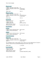
Page 8: ...cene Network Variables nvoScene LonMark network variable type name SNVT_scene LonMark network variable type id 95 nviPreset LonMark network variable type name SNVT_preset LonMark network variable type...

Page 9: ...will trigger sending one of the values in the UCPTsceneValue list The index of the scene number matches the index of the value this means that it a scene recall is received for the scene number in UC...

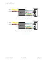
Page 10: ...t be extedended and the inputs and outputs should only be connected to switches or LED s as shown below OBS Activating switch 1 2 DI1 DI2 simultaneously will transmit a service pin message to the netw...

Page 11: ...1 DI 2 DI 3 DI 4 DI 5 DI 6 DO 1 DO 2 DO 3 0 V Svagstr mstryk PSW5036 TP FT 10 24 V d c Figur 4 Lonbox PSW5036 6 indgange 3 udgange DI 1 DI 2 DI 3 DI 4 DO 1 DO 2 DO 3 DO 4 0 V Svagstr mstryk PSW5044 T...

Page 12: ...5 C Opbevaringstemperatur 20 til 70 C Tilslutninger forsyning og bus 4 x 0 33 Tilslutning af svagstr mstryk 5 11 x 0 33 Indgange Kontaktsp nding 3 3 V d c Pull up 1 kOhm Indgangsimpedans 10 kOhm Str m...

Reviews: