Prolyte H30V Rigging Tower
Assembly Instructions
Prolyte Products Group © 2001
page 2 of 9
Prolyte has made every effort to ensure the accuracy of this manual, no liability will be accepted for errors.
Prolyte reserves the right to change or alter their products or manuals without prior notice.
No part of this manual may be reproduced in any form or by any means without prior written permission.
Prolyte Products Group · phone: +31-594-851515 · fax: +31-594-851516 · www.prolyte.com
4. IDENTIFICATION
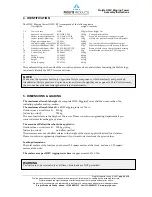
The H30V Rigging Tower (H30V-RT) is composed of the following parts:
Description
Code
weight
remarks
1, 2
Tower trusses
H30V
5.1kg/m1 Max. height 7 m
3
Square 30 3-way corner 60° RT-H30V-C002
12.2kg
V-shaped corner block
4
Layher spindel attachement ACC-Spin-ATT-30
2 kg
Pipe with trussclamps to adapt Screwjacks
5
Layher spindel, 40cm long
ACC-Spin-LAY-40
12 kg
Hot dip sinc plated screwjack, 20cm adjustable
6
Hinge part square truss
CCS6-H
0.58kg
7
Topblock rigging tower H30V RT-009H
12,2kg
Top section with removeable 30mm spigot
8
Stabelizer attachment H30V RT-STAB-H30V
2,7kg
Frame with clamps to attach bracing to trusses
9
Stabelizer attachment H30V RT-STAB-H30V-TOP
6,4kg
Frame with side-entry clamps to attach bracing
10
Stabelizer tube 60 mm
RT-T60-CC298CC
8kg
Stabelizer tube with conical CCS7 couplers
11
Conical Coupler
CCS6-600
0.14kg
12
Spigot
CCS6-603 0.04kg
13
Safety R-spring
CCS6-605
0.01kg
14
Spigot
CCS7-703 0.11kg
15
Safety R-spring
CCS7-705
0.01kg
The embossed ring on the ends of the conical coupler receivers, and stickers featuring the Prolyte logo
can clearly identify the MPT towers and truss.
5. DIMENSIONS & LOADING
The maximum allowable height
of a complete H30V Rigging Tower shall be no more than 7 m,
including spindles and top-section.
The maximum allowable load
to a H30V rigging tower of 7 m is:
Outdoor (max. wind force 8): 550 kg
Indoor (no wind):
700 kg
The max. load relates to the height of the tower. Please consult our engineering department if you
want to deviate from the given values.
The amount of Ballast that should be applied is:
Outdoor (max. wind force 8): 100 kg per leg
Indoor (no wind):
no ballast needed
The necessary amount of ballast relates to the height of the tower, applied load and load surface.
Please consult our engineering department if you want to deviate from the given values.
Loading dimensions:
The total surface of the load may not exceed 2,5 square meters at the front, and max. 1,25 square
meters at the sides.
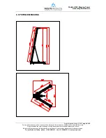
The surface area per H30V rigging tower base
is approximate
3.80x 3.20m
NOTE
Make sure the system is built only of genuine Prolyte components, which are clearly and positively
identified as Prolyte products. Copies do exist, and even though they may appear to fit to Prolyte trusses,
they do not have identical strength and safety characteristics.
WARNING
Payloads are to be vertical only at all times. Side loads are NOT permitted.


