background image


4.2 Noise  emission


Acoustic  pressure  level (EN 11202): 
Idling  at maximum  speed    73,4 dB (A)


The specified  values  are emission 
levels  and are not necessarily  to be 
seen as safe operating  levels.


As workplace  conditions  vary,  this


information  is intended  to allow the 
user to make  a better  estimation  of the 
hazards  and risks involved  only.


4.3 Content  of delivery


Four  way tool post  
Set of change  gears  
MT-5  fixed centre  
MT-3  fixed centre


160mm  3-jaw universal  chuck


Chuck  guard


Splash  guard


Assembly  kit


Operating  manual


Spare  parts list.


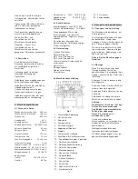
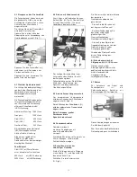
4.4 Machine  Description


Fig 1


1…


Change Gear Cover 

2…


Emergency Stop Switch 

3… Control Panel 
4…


Coolant pump switch


5… Feeding Selection Knob 
6…


Clutch Overload 

7… Stopping Plate 
8… Carriage Handwheel 
9… Half Nut Lever 
10… Carriage/Cross Feed Lever 
11…


Tailstock Barrel Handwheel


12…


Tailstock Clamp Lever


13…


Tailstock Center Lock


14…


Working Lamp 

15… Compound Slide Handwheel 
16… Coolant Hose 
17…


Tool Post


18…


Cross Slide


19…


Carriage


20…


Chuck Guard 

21… Lathe Chuck 
22…


Foot Swhich


23…


Cabinet Stand


5.  Transport  and start  up


5.1 Transport  and installation


The machine  will be delivered  in a 
closed  crate.


For transport  use a forklift  or hand 
trolley.  Make sure the machine  does 
not tip or fall off during  transport.


The machine  is designed  to operate  in 
closed  rooms.


Make  sure the machine  cannot  tip!


5.2 Assembly


If you notice  transport  damage  while 
unpacking,  notify  your  supplier 
immediately.  Do not operate  the 
machine!


Dispose  of the packing  in an 
environmentally friendly  manner.


Clean  all rust protected  surfaces  with 
petroleum,  diesel  oil or a mild solvent.


Unbolt  the lathe from the shipping


crate  bottom.


Use heavy  duty fibre belt for lifting the 
machine  off the pallet.


Caution:


The machine  is heavy  (387 kg)! 
Assure  the sufficient  load  capacity 
and proper  condition  of your lifting 
devices.


Never  step underneath  suspended 
loads.


To avoid  twisting  the bed, make  sure 
the setup  surface  is absolutely  flat and 
level.


Loosen  mounting  bolts,  shim and 
tighten  mounting  bolts if needed.


The machine  must be level to be 
accurate. 
 

5.3 Mains  connection


Mains  connection  and any extension 
cords  used must comply  with 
applicable  regulations.


The mains  voltage  must comply 
with the information  on the machine 
licence  plate.


The mains connection  must have a


10 A surge-proof  fuse.


Only use power  cords  marked


H07RN-F.


Connections  and repairs  to the 
electrical  equipment  may only be 
carried  out by qualified 
electricians.


5.4 Initial lubrication 


The machine  must  be serviced  at 
all lubrication  points before  it is 
placed into service!


Failure  to comply  may cause  serious 

damage.


(see chapter  8 for lubrication)


5.5 Starting  operation


Before  starting  the machine  check  the 
proper  chucking  (see chapter  6).


Always  close the chuck  guard  and 
pulley  cover before  you start the 
machine.


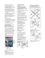
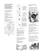
You can start the machine  with the


green ON-button  (A, Fig 2).


The red OFF-button  (B) stops  the 
machine.


The speed can be adjusted by turning 
the switch (E). 


Use buttons  (C, D) to reverse  the 
spindle  direction.


Fig 2 


The RPM will be shown on the display 
(F). 

The emergency stop button (2, Fig 1) 
stops all machine functions. 

Turn emergency stop button clockwise 
to reset. 

Summary of Contents for 947VA

Page 1: ...Lathe Metalldrehbank Tour m taux 07 2019 947VA Schweiz Suisse JPW TOOL AG Ackerstrasse 45 CH 8610 Uster Switzerland www promac ch France TOOL FRANCE SARL 9 Rue des Pyr n es 91090 LISSES France www pro...

Page 2: ...6 42 EC Machinery Directive Maschinenrichtlinie Directive Machines 2014 30 EU electromagnetic compatibility elektromagnetische Vertr glichkeit compatibilit lectromagn tique designed in consideration o...

Page 3: ...ring faults This warranty does not cover any defects which are caused either directly or indirectly by incorrect use carelessness damage due to accidents repairs or inadequate maintenance or cleaning...

Page 4: ...stallation may be carried out by a qualified electrician only Have a damaged or worn power cord replaced immediately Never place your fingers in a position where they could contact any rotating parts...

Page 5: ...in an environmentally friendly manner Clean all rust protected surfaces with petroleum diesel oil or a mild solvent Unbolt the lathe from the shipping crate bottom Use heavy duty fibre belt for liftin...

Page 6: ...ay break and fly off in rotation Fig 3 Fig 3 Avoid long workpiece extensions Parts may bend Fig 4 or fly off Fig 5 Use tailstock or rest to support Fig 4 Fig 5 Avoid short clamping contact A Fig 6 or...

Page 7: ...t the lowest spindle speed When the tool reaches the end of cut stop reverse the motor and at the same time back the tool out of the part so that it clears the thread Reverse the motor direction to al...

Page 8: ...he graduated scale Fig 15 7 5 Three jaw universal chuck With this universal chuck cylindrical triangular and hexagonal stock may be clamped Fig 16 Fig 16 To hold big diameter stock a set of 3 OD chuck...

Page 9: ...P L2 Mobilgrease Special 10 grease teeth of change gears 11 grease rack over entire length 12 grease teeth of headstock gears Fig 21 Fig 21 9 Trouble shooting Motor doesn t start Chuck guard open clos...

Page 10: ...d Inspektion Schmierungsplan 9 St rungsabhilfe 10 Umweltschutz 11 Lieferbares Zubeh r 1 Konformit tserkl rung Wir erkl ren in alleiniger Verantwortlichkeit dass dieses Produkt mit den auf Seite 2 ange...

Page 11: ...hig sein Beachten Sie dass die elektrische Zuleitung nicht den Arbeitsablauf behindert und nicht zur Stolperstelle wird Den Arbeitsplatz frei von behindernden Werkst cken etc halten Seien Sie aufmerk...

Page 12: ...fang Vierfach Stahlhalter Wechselr dersatz MK 5 feste K rnerspitze MK 3 feste K rnerspitze 160mm Universal Dreibackenfutter Futterschutz Spritzschutz Montagezubeh r Gebrauchsanleitung Ersatzteilliste...

Page 13: ...Aus Taster durch Drehung im Uhrzeigersinn 6 Betrieb der Maschine Achtung Vor R st und Einstellarbeiten muss die Maschine gegen Inbetriebnahme gesichert werden Netzstecker ziehen Kontrollieren Sie vor...

Page 14: ...idwerkzeug der Stabilit t der Werkst ck Einspannung der Spantiefe und der gew nschten Oberfl chenqualit t ab 6 5 Automatischer L ngsvorschub Der automatische L ngsvorschub wird durch Anheben des Schal...

Page 15: ...t ck im Drehherz spannen und zwischen den Spitzen einspannen Die Mitnahme erfolgt mittels Aufspannscheibe und Mitnehmerbolzen Fig 13 Fig 13 Schmieren Sie die Reitstock K rnerspitze um ein Verreiben zu...

Page 16: ...w lzgelagert und f r alle Drehzahlen ber 500 U min unbedingt zu empfehlen Fig 18 Zum Auswerfen des Mitlaufk rners die Reitstockpinole ganz zur ckkurbeln 7 8 Steh und Laufl nette Stehl nette Die Stehl...

Page 17: ...tzsicherung pr fen Motor Schalter oder Kabel defekt Elektrofachkraft kontaktieren Maschine vibriert Werkst ck unwuchtig Unwucht ausgleichen Drehzahl reduzieren Werkst ck instabil gespannt Einspannl ng...

Page 18: ...s conform ment aux lignes directrices indiqu es page 2 Lors de la construction les normes suivantes ont t respect es 2 Prestations de garantie TOOL FRANCE SARL garantit que le les produit s fourni s e...

Page 19: ...laisser la machine en marche sans surveillance Arr ter la machine avant de quitter la zone de travail Eloigner de la machine toutes personnes incomp tentes surtout les enfants Ne pas mettre la machine...

Page 20: ...ne Fig 1 1 Protection des pignons 2 Arr t coup de poing 3 Panneau de contr le 4 Inter de la pompe de lubrification 5 S lecteur d avance 6 Embrayage de surcharge 7 Stopper 8 Manivelle du tra nard 9 Lev...

Page 21: ...sens des aiguilles d une montre 6 Fonctionnement de la machine Attention Avant les travaux d quipement et de r glages la machine doit toujours tre assur e contre la mise en route D brancher la machin...

Page 22: ...tabilit du serrage de la pi ce d oeuvre de la profondeur d usinage et de la qualit souhait e de la surface de travail 6 5 Avance longitudinale automatique Pour d clencher l avance longitudinale automa...

Page 23: ...Fixer la pi ce d uvre dans le toc puis entre les pointes L entra nement se fait par le plateau et la broche d entra nement Fig 13 Fig 13 Afin d viter le frottement graisser la contre pointe et la poin...

Page 24: ...s fixe et mobile Lunette fixe La lunette fixe sert principalement soutenir les pi ces longues et garantit un usinage s r exempt de vibrations La lunette fixe est mont e sur le banc du tour et bloqu e...

Page 25: ...e mandrin ouvert Fermer le prot ge mandrin Pas de courant V rifier le fusible D faut au moteur bouton ou c ble Contacter un lectricien qualifi Vibrations de la machine Pi ce d uvre non quilibr e Equil...

Page 26: ......

Reviews: