9
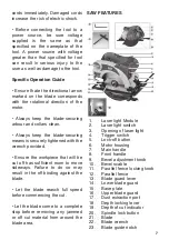
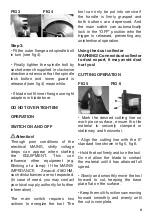
FIG 3
FIG 4
Step 3:
• Fit the outer flange and spindle bolt
in turn (see fig 4).
• Finally tighten the spindle bolt by
socket wrench supplied in clockwise
direction and ensure that the spindle
lock button and lower guard is
released (see fig 4) meanwhile.
• If blade not fit inner flange use right
adapters in blade bore.
DO NOT OVER-TIGHTEN!
OPERATION
SWITCH ON AND OFF
Attention!
Through poor conditions of the
electrical MAINS, shrtly voltage
drops can appear when starting
the EQUIPMENT. This can
influence other equipment (eg.
Blinking of a lamp). If the MAINS-
IMPEDANCE
Zmax<0.418OHM,
such disturbances are not expected.
(In case of need, you may contact
your local supply authority for further
information).
The main switch requires two
actions to energize the tool. The
tool can only be put into service if
the handle is firmly grasped and
both buttons are depressed. And
the main switch can automatically
lock in the “OFF” position whn the
trigger is released, preventing any
unintentional operation.
Using the dust collector
WARNING! Connect dust collector
to dust export, it may avoid dust
hurt you!
CUTTING OPERATION
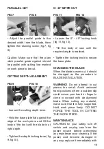
FIG 5
FIG 6
• Mark the desired cutting line on
work piece surface, ensure the tile
material is securely clamped or
stationary and horizontal.
• Align the cutting line with the 0º
standard line shown in fig 5, fig 6.
• Hold the tool firmly and turn the tool.
Do not allow the blade to contact
the material until it has attained full
speed.
• Slowly and smoothly move the tool
forward to cut, keeping the base
plate flat on the surface.
• Keep the multi-function saw moving
forward smoothly and evenly until
the cut is complete.


