background image

Connecting the DC Cables

DC connections must be securely fastened and all connections must be tight to avoid risk
of fire. Connect the DC cables from the inverter to the battery as noted in the following steps:

1. Switch the On/Off switch to the Off position.

2. Route the DC cables from the inverter toward the battery.

3. For an ABYC E-11 compliant installation, connect a customer supplied DC fuse or
circuit breaker in the positive side of the circuit within 7 inches of the battery. This
protects your battery and wiring in case of an accidental shorting (Please see
Specifications Table in this Manual for correct sizing).

4. Open the DC fuse or turn off the circuit breaker.

5. Install one connector on the POSITIVE (+) cable to the POSITIVE DC terminal on the inverter.

6. Install the other connector to the POSITIVE (+) terminal DC fuse or DC circuit breaker. Use
a wrench to tighten the connection. Test that the cable is secure and the connection is tight.

7. Attach a short DC cable from the unconnected end of the DC fuse or DC circuit
breaker. Tighten appropriately.

8. Observing polarity carefully, connect the end of the fused cable to the POSITIVE (+)
terminal of the battery. Tighten this connection to the battery manufacturer’s recommended
torque. You may replace the fuse now or turn the DC circuit breaker on.

9. Connect one connector on the NEGATIVE (-) cable to the NEGATIVE (-) battery terminal.
Tighten the connection and assure the cable is secure.

10. Check that the polarity of the DC connection is correct: positive (+) on the inverter is
connected to the positive (+) on the battery and negative (-) is connected to the negative (-).

IMPORTANT: The next step is the last cable connection you will need to make in mounting
the TruePower inverter. A spark is normal when this connection is made!

11. Connect the other connector of the NEGATIVE (-) cable onto the NEGATIVE (-) terminal
on the TruePower Inverter.

12. Use a wrench to tighten the nut. Test that all cable connections are tight.

Connecting The AC Hardwire

The 2000, 2500 and 3000watt models have a Terminal strip, located on the front panel,
allow a qualified electrician or professional installer to bring in 1 or 2 AC hardwires
consisting of a line, neutral and ground wire (L,N,G). The 2000 and 2500 watt models
require a 12 gauge hardwire, while the 3000w model requires a 10 gauge wire. 

All

outlets installed remotely to this hardwire connection must be GFCI receptacles,
or remotely GFCI protected.

9

I n s t a l l a t i o n   G u i d e l i n e s

10

Te s t i n g   Yo u r   I n v e r t e r

Performing Checks Prior to Operation

Before starting up your inverter, ensure these conditions are met:

Verify the On/Off switch is in the Off position

Verify the Positive (+) battery cable is connected to the positive (+) battery terminal.

Verify the Negative (-) battery cable is connected to the negative (-) battery terminal.

Verify the battery voltage is within the proper range for this unit (roughly 10-15.5 volts DC).

Verify the DC fuse is in tact.

Testing Installation

When you are ready to test your installation and operate the TruePower Inverter, close
the DC fuse or the DC circuit breaker to supply DC power to the TruePower inverter.

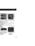
Display Functions of the LED Light Pattern:

The ON/OFF switch turns the TruePower inverter to ON or to OFF:

- In the On position, the Inverter Power LED light illuminates Green. The TruePower begins
inverting and provides AC power.
- In the Off position, the TruePower Inverter draws no current from the battery. None of
the front panel LED lights are illuminated.
- The Fault Light Illuminates Red when a fault conditions such as over temperature, output
overload, or battery low voltage occurs.

To test the TruePower Inverter:

1. Turn the On/Off switch to the ON position.
    The Inverter/Fault LED light illuminates Green.
2. Plug an appliance of equal watts or less into the AC outlet.
3. Turn the appliance ON to verify that it operates.

If the Inverter/Fault light illuminates Red, see the TruePower Inverter “Troubleshooting”
section.

Testing of the GFCI

1. Turn the On/Off switch to the ON position.
2. Plug a test lamp into the GFCI outlet.
3. Press the “test” button located on the GFCI outlet.
4. The “reset” button should pop out and the power to the test lamp should turn off. If the lamp
does not shut off and remains on, or if the reset button does not pop out, the GFCI receptacle
is defective. Please call factory service at 1-800-824-0524 for replacement or service.
5. To resume regular operation, push the “reset” button to return to regular operation.

Summary of Contents for TruePower 05150

Page 1: ...rter 00 Watt 05174 24 VDC Input 1700 Watt 110 VAC Output Inverter 00 Watt 05204 24 VDC Input 2000 Watt 110 VAC Output Inverter 00 Watt 05254 24 VDC Input 2500 Watt 110 VAC Output Inverter 00 Watt 05304 24 VDC Input 3000 Watt 110 VAC Output Inverter OnBoard Solutions A ProMariner Company roMariner TruePowerInverterSeries 500 3000Watt High Power Models Owner Manual Installation Guide Heavy Duty Mari...

Page 2: ...tulations on your recent purchase of a TruePower Inverter ading the Marine industry in Power Conversion for over 30 years ProMariner s On oard Solutions division has designed a complete line of Power Inverters ranging from 0 to 3 000 watts specifically for Marine Industrial use TruePower Inverters will onvert your OnBoard 12Vdc Battery power to 110Vac Household Power to run TV s ptops Gaming Syste...

Page 3: ...12V 12V 24V 12V 24V 12V 24V 12V 24V ontinuous Power 1500W 1700W 2000W 2500W 3000W urge Power 3000W 3400W 4000W 5000W 6000W utput Waveform Modified Sine Wave C Output voltage 115V 10 C Output amps up to continous 13 6 15 5 18 2 22 7 27 3 C Input Voltage 10V 15V 10V 15V 20V 30V 10V 15V 20V 30V 10V 15V 20V 30V 10V 15V 20V 30V C Input Amps up to 150A 170A 85A 200A 100A 250A 125A 300A 150A ficiency 85 ...

Page 4: ...nstall in compartments ontaining gasoline fueled engines or gasoline tank or in areas where ignition otected equipment is required WARNING Do not mount the inverter above or below your batteries WARNING Electrical shock and fire hazards n Board Solutions a ProMariner Company recommends all wiring be done by ualified personnel Disconnect all AC and DC power sources to prevent accidental hock Disabl...

Page 5: ...The fan will run at full speed when the inverter is powering a higher rated appliance Possible Cause The ambient temperature is high Solution No action The fan will run at a higher ambient temperature to keep the inverter cool Low Battery alarm sounds continuously Possible Cause Bad wiring or connection Solution Tighten and clean all DC connections Power tool will not start Possible Cause Large st...

Page 6: ...bulletspointingoutdigital argraphdisplay on offswitch ledlocationsetc PleaseReferenceTablebelowforfeatures ON Off Switch turns the inverter to ON OFF Power light illuminates when inverter is on Fault Light illuminates Red for fault conditions such as over temperature output overload or battery low voltage Two GFCI Protected AC Outputs to power connected appliances Reset and Test monthly capabiliti...

Page 7: ...rload check the AC wiring and reset the breaker by turning the ON Off switch to Off and then back to ON Possible Cause GFCI has tripped Solution Clear the ground fault and reset the GFCI by pressing the reset on the GFCI button No AC output voltage Red Fault LED light is illuminated roubleshooting his section is designed to accommodate you in identifying and troubleshooting ommon problems that may...

Page 8: ...on Select an appropriate mounting location and orientation Hold the inverter against the mounting surface mark the position of the mounting crews and then remove the inverter Drill pilot holes for the four mounting fasteners Use caution prior to drilling or cutting ensure proper clearance from existing wiring and hardware Fasten the inverter to the mounting surface with four hardware fasteners ote...

Page 9: ...lly reset to operating levels perating Several Appliances at the Same Time you are going to operate several appliances at the same time turn them on dependently after you have powered up the inverter This action ensures that the uePower does not have to deliver the starting current for all of the appliances at nce The TruePower can accommodate several appliances at once as long as they o not excee...

Page 10: ...quirement of ur inverter This battery bank requires a attery charging system youareusingdifferentbatteries orneedtousemorethattwobatteries werecommend at you set up two separate battery banks and use them alternately Battery selector witches are available from Marine and RV Dealers which allow the user to select etween two banks of batteries or use both in parallel or disconnect both banks from e ...

Page 11: ...provides AC power n the Off position the TruePower Inverter draws no current from the battery None of e front panel LED lights are illuminated TheFaultLightIlluminatesRedwhenafaultconditionssuchasovertemperature output verload or battery low voltage occurs test the TruePower Inverter Turn the On Off switch to the ON position The Inverter Fault LED light illuminates Green Plug an appliance of equal...

Reviews: