7
3. OPERATION
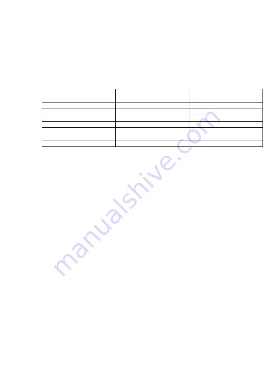
3.1 VACUUM SETTING GUILDLINES
Products
Vacuum time/Sec.
Storage life when stored at
2 ~ 6
℃
/day
Fresh meat
30
10
Pork
30
10
Beef
30
30
Meat with liquid
15 ~ 30
14
Pasta 3
~
9
21
Sliced sausage
15
10
Cold cuts
9 10
~
21
3.2 BASIC OPERATING INSTRUCTIONS
Turn on the main switch and the LED display shows the operation menu, at this
time, machine is ready to operate.
Place the product to be packaged in a vacuum pouch. Place the bag in chamber with
the open end of bag across the sealing bar. (With a package that doesn’t completely
fill the chamber, place provided flat plates in the chamber to shorten vacuum time.)
Close the lid to start the cycle, the lid will open automatically when cycle is
completed.
Take out the sealed product from vacuum chamber.You are ready to start the next
cycle.
After all packaging is completed, please let the vacuum pump run for about 15
minutes, then turn off the main switch to shut down the machine.
3.3 OPTIONAL DEVICE
3.3.1 GAS FLUSHING UNIT
If your machine is equipped with an optional gas flush system please note the
following points.
Make sure you have connected a regulated gas source to the gas inlet fitting
Do not set your regulator for a pressure of greater than 40psi
Place the open end of your package in front of the gas inlet nozzles
Do not tuck the bag under the gas nozzles
Summary of Contents for Promax DC-640
Page 19: ...16 ...
Page 23: ...20 5 3 PNEUMATIC DIAGRAM ...
Page 24: ...21 5 4 ELECTRICAL DIAGRAM FB ...
Page 25: ...22 5 3 ELECTRICAL DIAGRAM TB ...
Page 27: ...6 1 BODY 24 DC64100000 Body Diagram ...
Page 29: ...6 2 WORKING BED BOTTOM 26 C C Working bed Bottom Diagram DC64200000 ...
Page 32: ...6 3 1 CUSHION BAR FB 29 Cushion Bar Diagram DC642FB000 ...
Page 34: ...6 3 2 CUSHION BAR FBG 31 DC642FBG00 Cushion Bar Diagram ...
Page 36: ...6 3 3 CUSHION BAR FBPK 33 DC642PK000 Cushion Bar Diagram ...
Page 38: ...6 3 4 CUSHION BAR FBPKG 35 DC642PKG00 Cushion Bar Diagram ...
Page 40: ...6 3 5 SEALING BAR BOTTOM FBTB 37 DC642TB000 Sealing Bar Bottom Diagram ...
Page 42: ...6 3 6 SEALING BAR BOTTOM FBTBG 39 DC642TBG00 Sealing Bar Bottom Diagram ...
Page 44: ...6 3 7 SEALING BAR BOTTOM FBTBPK 41 DC642TK000 Sealing Bar Bottom Diagram ...
Page 46: ...6 3 8 SEALING BAR BOTTOM FBTBPKG 43 DC642TKG00 Sealing Bar Bottom Diagram ...
Page 48: ...6 4 CHAMBER LID DIAGRAM 45 Chamber Lid Top Diagram DC80300000 ...
Page 50: ...6 5 1 SEALING BAR TOP FB 47 D64312A00 Sealing Bar Top Diagram ...
Page 53: ...6 5 2 SEALING BAR TOP PK 50 DC64350A00 Sealing Bar Top Diagram ...
Page 56: ...53 6 6 ELECTRICAL BOX FB 6 6 ELECTRICAL BOX TB ...


